Liquid resin transfer molding system and forming method thereof

A technology of transfer molding and liquid resin, which is applied in the field of liquid molding of resin-based composite materials. It can solve the problems of excessive porosity of composite parts, high local compaction, and increase the difficulty of exhausting preforms, so as to reduce porosity. rate effect

Active Publication Date: 2016-04-13
AVIC COMPOSITES
View PDF5 Cites 7 Cited by
  • Summary
  • Abstract
  • Description
  • Claims
  • Application Information

AI Technical Summary

Problems solved by technology

As the resin transfers, the gas contained in the resin will be wrapped inside the part, resulting in the porosity of the molded part being out of tolerance
In addition, the local compaction of the preform of parts with complex structures is high, resulting in the gas wrapped inside the preform cannot be fully discharged during the vacuuming stage, resulting in the porosity of the final composite part exceeding the standard
Thirdly, the preform after toughening / setting treatment is used, such as toughening the preform by weft toughening, spraying a sizing agent on the surface of the fiber, or placing a toughening material between the fiber layers. The toughening material does not have The characteristics of air conduction will also increase the difficulty of exhausting the preform, resulting in the porosity of the final formed composite parts exceeding the standard

Method used


Image

  • Liquid resin transfer molding system and forming method thereof
  • Liquid resin transfer molding system and forming method thereof

Examples


Embodiment 1

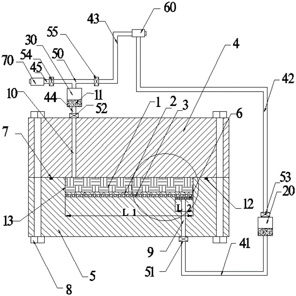
[0074] The preform 1 is a composite laminate structure, the material system is CF3031 / BA9912, and the fiber volume content of the material is 55%±3%; CF3031 is a T300 grade carbon fiber fabric with a specification of 3K produced by Shandong Weihai Development Company, and BA9912 resin It is a special resin developed for the liquid molding process by AVIC Composite Materials Co., Ltd. The external dimensions of the parts are: 500mm×500mm×3.65mm (length×width×thickness), and the design requires the porosity of the parts to be ≤1.5%. System layout such as figure 1 .

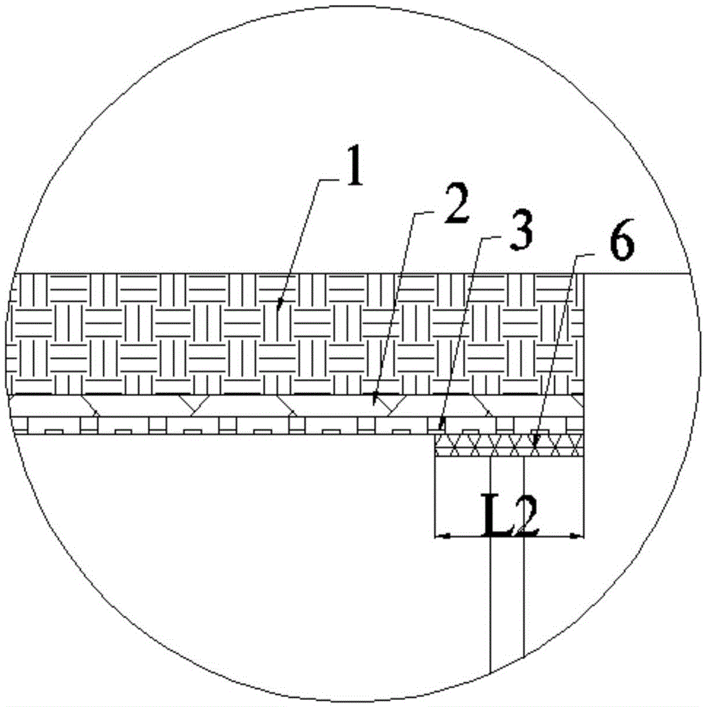
[0075] 1) On the side of the glue outlet channel 9 of the lower half-mold 5 close to the mold cavity 13, place the glue-permeable layer 6, the air-conducting layer 3 and the air-blocking glue layer 2 in sequence. The glue-penetrating layer 6 is a Q235 steel plate with a thickness of 5mm, including 5mm×5mm Density through holes, the length is 20mm, the air guide layer 3 is the greenflow guide net of Airtech Company,...

Embodiment 2

[0098] It was carried out as described in Example 1, and the only difference between Example 2 and Example 1 was that the material system in Example 2 was T800 / 5284, and the fiber volume content of the material was 56%±3%. Among them, T800 is the T800 carbon fiber with a specification of 12K produced by Toray Corporation of Japan, and 5284 resin is a special resin developed by AVIC Composite Materials Co., Ltd. for the liquid molding process. ×thickness); the design requires that the porosity content of the part is ≤2%. System layout such as figure 1 shown.

[0099] 1) On the side of the glue outlet channel 9 of the lower half-mold 5 close to the mold cavity 13, place the permeable glue layer 6, the air guide layer 3 and the air resistance glue layer 2 in sequence. The glue permeable layer 6 is an LY12CZ aluminum plate with a thickness of 3mm, including 3mm×3mm Density through holes, the length is 50mm, the air-guiding layer 3 is Airtech’s 90flow air-guiding mesh, and the ai...


PUM

PropertyMeasurementUnit
thicknessaaaaaaaaaa
lengthaaaaaaaaaa

Abstract

The invention provides a liquid resin transfer molding system and a forming method thereof, belongs to a resin matrix composite liquid forming technology, and relates to a method capable of reducing porosity of composites formed by a resin transfer molding process. An air permeable glue stopping layer, an air guiding layer and a glue permeating layer are arranged in a preform glue outlet region, and gas in a preform and gas in the resin can be discharged fully. By the air permeable glue stopping layer, the air guiding layer and the glue permeating layer which are arranged in the mold preform glue outlet region, the gas in the preform and the gas in the resin are discharged fully in a resin transfer process, the porosity of the composites formed by the resin transfer molding process is reduced remarkably, the forming quality is improved, and the production cost is reduced.

Description

technical field [0001] The invention belongs to the liquid molding technology of resin-based composite materials, and relates to a resin transfer molding method for reducing the porosity of composite materials. Background technique [0002] Carbon fiber reinforced resin-based composite materials have unique advantages such as light weight, high specific strength, high specific modulus, good fatigue fracture resistance, corrosion resistance, and easy large-area integral forming. The amount of key materials used in equipment has also become one of the symbols of the advanced nature of aviation equipment. [0003] Resin transfer molding technology, referred to as RTM technology (ResinTransferMolding) is a liquid molding composite material manufacturing technology widely used in aviation, aerospace and other fields in recent years. The principle is to lay a dry fiber preform designed according to the performance and structural requirements in the rigid mold cavity, and then use...

Claims


Application Information

Patent Timeline
Patent Type & Authority Applications(China)
IPC IPC(8): B29C70/48B29C70/54
CPCB29C70/48B29C70/54
Inventor 黄峰刘强马金瑞赵龙
Owner AVIC COMPOSITES
Why Eureka
Try Eureka