
Axial-flow type centrifugal fan

A centrifugal fan and axial flow technology, which is used in mechanical equipment, non-variable-capacity pumps, machines/engines, etc., can solve the problems of limited wind pressure adjustment range, can not guarantee the safety and performance of fans, and achieves The effect of reducing maintenance frequency, occupying small space and prolonging service life

Inactive Publication Date: 2014-08-13
江苏兆年智能科技有限公司
View PDF7 Cites 4 Cited by
  • Summary
  • Abstract
  • Description
  • Claims
  • Application Information

AI Technical Summary

Problems solved by technology

However, there is currently no fan on the market that can be used in these fields. It can only be simply modified on site and added some protective facilities to ensure the safety of use.
However, these modified facilities cannot well guarantee the safety and performance of the fan.
[0004] The patent CN201925201U discloses a fan. Although it adopts the design of isolating the motor from the workpiece and the fluid, the air inlet uses a cylindrical air inlet with a common impeller. The air pressure adjustment range of this design is limited.

Method used


Image

  • Axial-flow type centrifugal fan
  • Axial-flow type centrifugal fan
  • Axial-flow type centrifugal fan

Examples


Embodiment Construction

[0021] The present invention will be further described below in conjunction with the accompanying drawings.

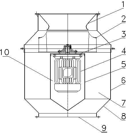
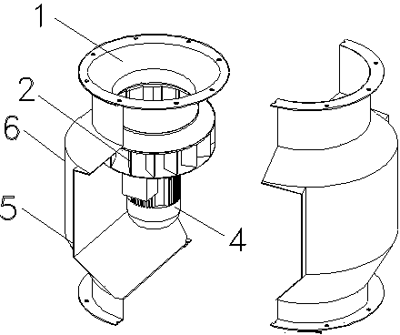
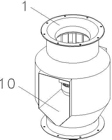
[0022] Such as Figure 1-Figure 3 As shown, an axial-flow centrifugal fan includes a housing 8, the upper and lower ends of the housing 8 are respectively provided with an air inlet 1 and an air outlet 9, and the housing 8 includes an outer wall 6 that can form an air duct 7 And the inner wall 5, the centrifugal impeller 2 communicating with the air passage 7 is arranged below the air inlet 1, and the support plate 3 is arranged in the cavity 10 surrounded by the inner wall 5, and the support plate 3 is fixed There is a motor 4, the motor shaft of which passes through the support plate 3 and is connected to the centrifugal impeller 2, and the air inlet 1 is trumpet-shaped. By isolating the motor 4 from the workpiece and fluid, it can well play the role of waterproof, dustproof, explosion-proof and heat insulation, reduce the maintenance times of the motor 4, improve w...


PUM


Abstract

The invention discloses an axial-flow type centrifugal fan. The axial-flow type centrifugal fan comprises a shell, the upper end and the lower end of the shell are provided with an air inlet and an air outlet respectively, the shell comprises an outer wall and an inner wall which are capable of forming an air channel, centrifugal impellers communicated with the air channel are arranged below the air inlet, a support plate is arranged in a hollow cavity formed by surrounding of the inner wall, a motor is fixed on the support plate, and a motor shaft of the motor penetrates the support plate and is connected with the centrifugal impellers. By adopting the horn-shaped air inlet and the centrifugal impellers matched with the same, and since the centrifugal impellers are specially designed and manufactured and can be assembled with the corresponding horn-shaped air inlet, the problem of low static pressure of an axial-flow type fan is solved, an adjusting range of wind pressure is enlarged from 10Pa to 3000Pa, the trouble that smoke in tunnels cannot be exhausted smoothly is overcome, the problems of large centrifugal fan size and incapability of exhausting axially are solved, and advantages of the axial-type fan and a centrifugal fan are creatively combined.

Description

technical field [0001] The invention relates to a fan, in particular to an explosion-proof, waterproof and heat-insulating axial flow centrifugal fan. Background technique [0002] A fan is a machine that relies on input mechanical energy or electrical energy to increase gas pressure and discharge gas. It is widely used in ventilation, dust removal and cooling of factories, mines, tunnels, cooling towers, vehicles, ships and buildings, boilers and industrial furnaces. Ventilation and induction of kiln, cooling and ventilation of air conditioning equipment and household appliances, drying and sorting of grain, wind tunnel wind source and inflation and propulsion of hovercraft, etc. When the fan is working, because the gas flow rate is low and the pressure changes little, it is generally not necessary to consider the change of the gas specific volume, that is, the gas is treated as an incompressible fluid. [0003] Fans currently on the market are generally equipped with a ...

Claims


Application Information

Patent Timeline
IPC IPC(8): F04D29/40F04D29/26F04D29/58
Inventor 何群伟
Owner 江苏兆年智能科技有限公司
Learn More