Crystal ingot cutting device

A technology for cutting devices and crystal ingots, which is applied to fine working devices, working accessories, stone processing equipment, etc., and can solve problems affecting the quality of sliced ​​wafers and the weakening of wire saw cutting force, etc.

Inactive Publication Date: 2016-04-13
MOTECH INDUSTRIES
View PDF5 Cites 5 Cited by
  • Summary
  • Abstract
  • Description
  • Claims
  • Application Information

AI Technical Summary

Problems solved by technology

When the bow becomes larger due to the downward pressure of the ingot, the cutting force of the wire saw is weakened and obviously insufficient, thus affecting the quality of slices (such as wafers)

Method used


Image

  • Crystal ingot cutting device
  • Crystal ingot cutting device
  • Crystal ingot cutting device

Examples


no. 1 example

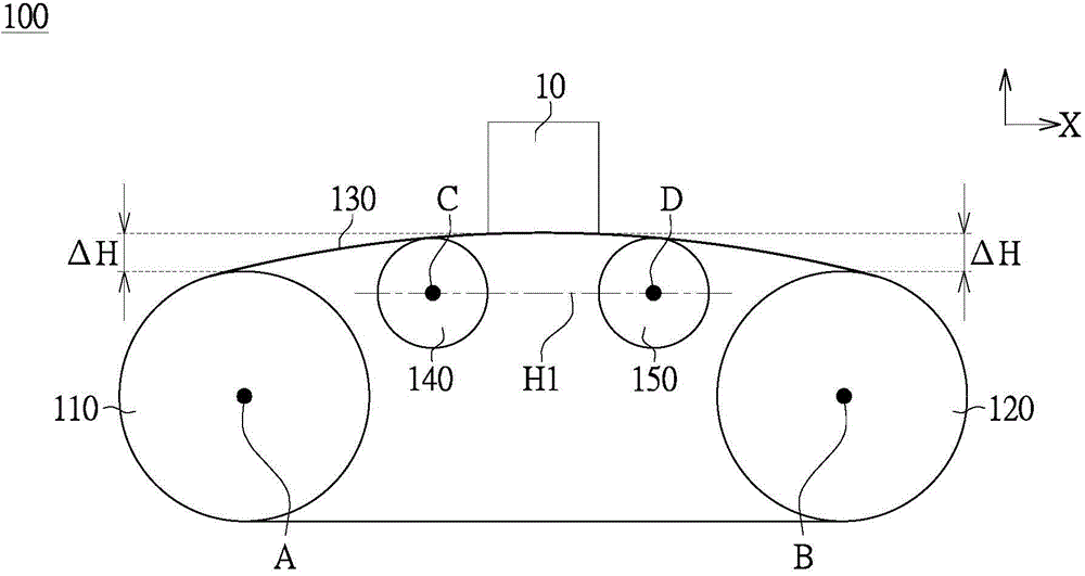
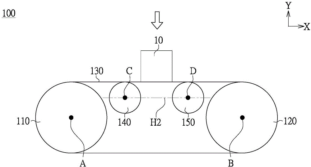
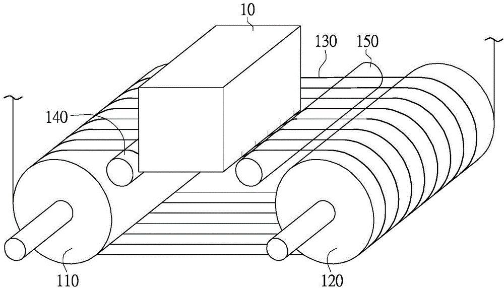
[0030] Please refer to Figure 1 to Figure 3 , which are respectively schematic diagrams of an ingot cutting device 100 according to an embodiment of the present invention. The ingot cutting device 100 includes a first main roller 110 , a second main roller 120 , a wire saw 130 and two auxiliary rollers 140 / 150 (namely the first auxiliary roller 140 and the second auxiliary roller 150 ). The first main roller 110 and the second main roller 120 are driven to rotate by a motor system (not shown in the figure), and the jigsaw 130 is driven by the first main roller 110 and the second main roller 120 . The first auxiliary roller 140 and the second auxiliary roller 150 are driven by the wire saw 130 . The auxiliary roller 140 / 150 is located between the first main roller 110 and the second main roller 120 , and the auxiliary roller 140 / 150 is not connected to the motor system, but driven by the wire saw 130 to rotate. For convenience of description, the auxiliary rollers 140 / ...

no. 2 example

[0042] Please refer to Figure 5 and Figure 6 , which shows a schematic diagram of an ingot cutting device 200 according to an embodiment of the present invention. The crystal ingot cutting device 100 includes a pair of first main rollers 210 , a pair of second main rollers 220 , a wire saw 230 and two auxiliary rollers 240 (ie, two first auxiliary rollers). Each first main roller 110 and each second main roller 120 are driven to rotate by a motor system, and the jigsaw 230 is driven by the first main roller 210 and the second main roller 220 to move back and forth at high speed. Each auxiliary roller 240 is located between the first main roller 210 and the second main roller 220 , and each is driven by the wire saw 230 to rotate. Although this embodiment takes four main rollers 210 / 220, a wire saw 230 and two auxiliary rollers 240 as an example, the method of cutting an ingot is similar to that of the first embodiment, the only difference being that two ingots 20 can be cu...


PUM


Abstract

A crystal ingot cutting device includes a first main roller, a second main roller, a wire saw and a first auxiliary roller. The first main roller and the second main roller are driven by a motor system to rotate. The wire saw is driven by the first main roller and the second main roller. The first auxiliary roller is located between the first main roller and the second main roller, and one side of the first auxiliary roller supports the wire saw in a horizontal direction. The first auxiliary roller is located at a first vertical position before a crystal ingot to be cut contacts with the wire saw, and the wire saw is limited by a groove on the first auxiliary roller in the horizontal direction. After the crystal ingot to be cut contacts with the wire saw, the first auxiliary roller moves to a second vertical position due to driving of the wire saw, and the first vertical position is higher than the second vertical position.

Description

technical field [0001] The invention relates to a crystal ingot cutting device, in particular to a crystal ingot cutting device with auxiliary rollers and a method thereof. Background technique [0002] The crystal ingot cutting device mainly uses a wiresaw to cut the crystal ingot, so as to cut the crystal ingot into a plurality of thin wafers. The wire saw is wound multiple times on two rollers arranged at appropriate intervals to achieve double-wire wire saw cutting. The phenomenon of saw bending is called bowsize. When the bow becomes larger due to the pressing down of the ingot, the cutting force of the wire saw is weakened and obviously insufficient, thereby affecting the quality of the slice (eg wafer). Therefore, how to reduce the bow and increase the cutting force of the wire saw without changing the existing cutting device so as to improve the quality of slicing is a problem to be solved at present. Contents of the invention [0003] The object of the present ...

Claims


Application Information

Patent Timeline
Patent Type & Authority Applications(China)
IPC IPC(8): B28D5/04B28D7/00
Inventor 叶宸夆杨尚伟
Owner MOTECH INDUSTRIES
Why Eureka
Try Eureka