
Light-source device, in particular for use in a micromirror device

A light source device and light source technology, applied in projection devices, optics, lasers, etc., can solve the problems of reduced resolution and disadvantages, and achieve the effect of reducing speckle effect

Inactive Publication Date: 2016-04-06
ROBERT BOSCH GMBH
View PDF6 Cites 11 Cited by
  • Summary
  • Abstract
  • Description
  • Claims
  • Application Information

AI Technical Summary

Problems solved by technology

Therefore, the resolving power is degraded in an unfavorable way

Method used


Image

  • Light-source device, in particular for use in a micromirror device
  • Light-source device, in particular for use in a micromirror device
  • Light-source device, in particular for use in a micromirror device

Examples


Embodiment Construction

[0019] In the different figures, identical parts are always provided with the same reference signs and are therefore usually also named or mentioned only once in each case.

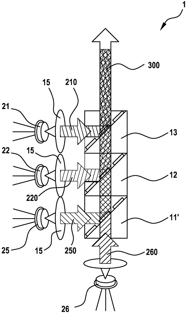
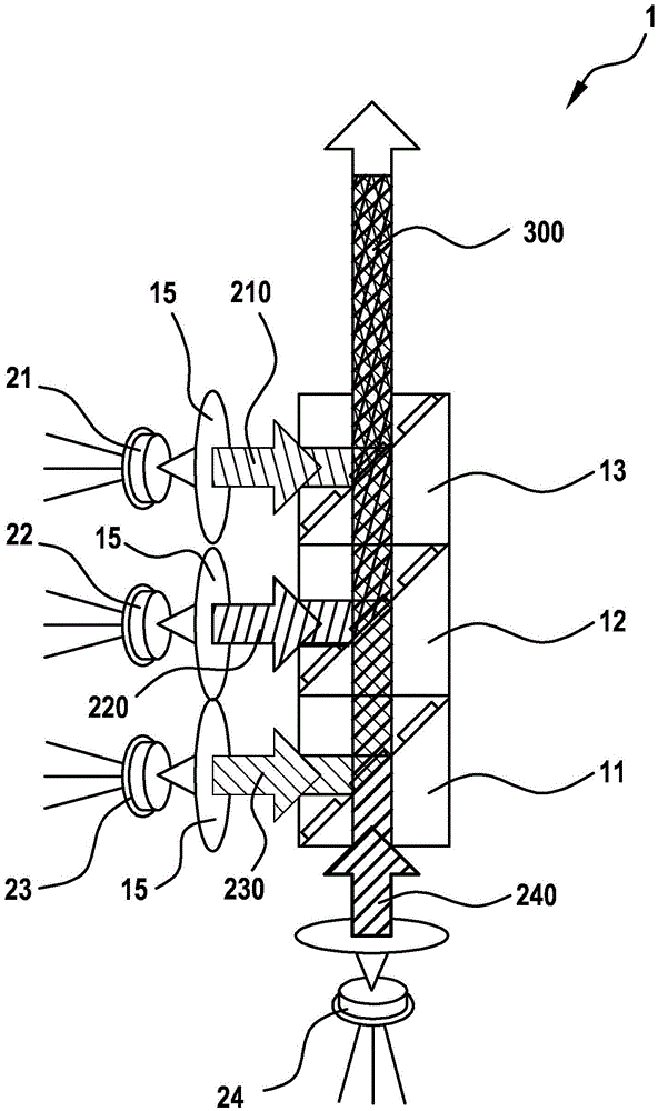
[0020] figure 1shows a light source arrangement 1 according to the prior art, which consists of a blue light source 22, a green light source 21 and two red light sources 25 and 26, wherein the blue light source emits light from the blue spectral range 220, the green light source Light from the green spectral range 210 is emitted, while the two red light sources emit light from the red spectral range 250 and 260 . For the light source device 1 that exists in the micromirror device, it is generally provided that the light from the red light source, the green light source and the blue light source 21, 22 and 25 overlap in such a way that they overlap to produce points with a defined color impression on the screen, The respectively desired color impression of the points is determined by the relative mixing r...


PUM


Abstract

The invention proposes a light-source device, in particular for use in a micromirror device, comprising a first red light source for emitting light in the red spectral range, a second red light source for emitting light in the red spectral range, a green light source for emitting light in the green spectral range and a blue light source for emitting light in the blue spectral range, and superposition means, wherein the superposition means are arranged in such a way that the light from the first red light source, the light from the second red light source, the light from the blue light source and the light from the green light source are superposed in a collinear manner to form a common light beam, the light from the first red light source having a wavelength different from that of the light from the second red light source.

Description

technical field [0001] The invention relates to a device according to the preamble of the main claim. Background technique [0002] Such light source arrangements are generally known in various variants and are also referred to as RGB modules. The development of powerful laser sources of increasingly smaller dimensions has made said light source devices an important component of micromirror devices or micromirror actuators, because despite their small spatial extension they can still Produces bright colored pixels. In this case, the light source arrangement only uses the light that is actually required. The micromirror arrangement can form in the future, for example, a core component of a pico-projector, a mini-barcode scanner or a device for endoscopy. However, the use of laser light is disadvantageous in that the high coherence of the laser light leads to speckle effects caused by interference on the screen towards which the light is directed. The use of semiconductor ...

Claims


Application Information

Patent Timeline
Patent Type & Authority Applications(China)
IPC IPC(8): G02B27/48G03B21/00G03B21/20
CPCG02B27/48G03B21/2013G03B21/2033G03B21/208G03B33/12H04N9/3129H04N9/3164H04N9/3173G02B27/1006G02B27/14H01S5/4012
Inventor L·劳舍尔F·菲舍尔G·皮拉德
Owner ROBERT BOSCH GMBH
Learn More