A high-energy multi-element ion implanter

An ion implanter and multi-element technology, which is applied in the direction of electrical components, discharge tubes, circuits, etc., can solve the problems of increasing the insulation distance, the physical size of the equipment, the poor uniformity of ion implantation, and the increase in the complexity of the structure, so as to ensure the ion beam current Purity, simple and compact structure, energy-enhancing effect

Active Publication Date: 2017-08-04
BEIJING SHUOKE ZHONGKEXIN ELECTRONICS EQUIP CO LTD
View PDF3 Cites 0 Cited by
  • Summary
  • Abstract
  • Description
  • Claims
  • Application Information

AI Technical Summary

Problems solved by technology

[0003] (1) The existing high-energy MeV energy ion implanters all use planetary batch targets, as shown in the attached figure 1 As shown, the single target needs to achieve both revolution and rotation, and there are technical problems of complex structure and poor uniformity of ion implantation
[0004] (2) In existing high-energy ion implanters, unaccelerated ions and neutral particles will be mixed in the fully accelerated ion beam and injected into the wafer in the target chamber together, causing energy pollution
However, the traditional electrostatic acceleration method increases the complexity of the structure with the increase of the voltage, and the increase of the insulation distance will greatly increase the physical size of the equipment, and the electrostatic acceleration is generally less than 500KV
For the special high-energy implantation process that requires MeV energy, the electrostatic acceleration method is no longer sufficient, and a new acceleration method is needed to accelerate the ion beam

Method used


Image

  • A high-energy multi-element ion implanter
  • A high-energy multi-element ion implanter
  • A high-energy multi-element ion implanter

Examples


Embodiment Construction

[0026] The present invention will be described in further detail below in conjunction with specific embodiments and accompanying drawings.

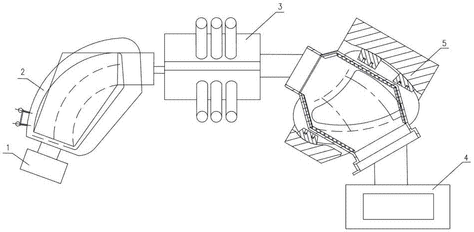
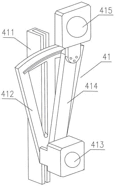
[0027] like Figure 2 to Figure 5 As shown, the present invention provides a high-energy multi-element ion implanter, including an ion source 1 , a mass analyzer 2 , a radio frequency acceleration system 3 and a target chamber 4 . The ion source 1 generates required ions, including: H, He, Ar, B, P, As, etc., which can be single charge, double charge and triple charge. The mass analyzer 2 receives the ions generated by the ion source 1, and realizes the ion screening function to obtain the required ions to ensure the purity of the ion species; at the same time, it partially focuses the transmitted ion beam to increase the beam transmission efficiency. After the mass analyzer 2 transmits the screened ion beam to the radio frequency acceleration system 3, the radio frequency acceleration system 3 accelerates the screened ion beam to accele...


PUM


Abstract

The invention discloses a high-energy multi-element ion injection machine. The machine comprises an ion source, a mass analyzer, a radio-frequency acceleration system and a target chamber, wherein the mass analyzer screens ion beams generated by the ion source and transmits the ion beams to the radio-frequency acceleration system for acceleration; the ion beams accelerated to be in a high-energy state through the radio-frequency acceleration system are transmitted into the target chamber to finish the ion beam injection; a target table motion mechanism is arranged in the target chamber and has two motion dimensions in horizontal and vertical directions; and the ion beam injection is finished in a two-dimensional scanning mode in the target chamber. The machine has the advantages of simple and compact structure, good ion injection uniformity and little ion injection energy pollution.

Description

technical field [0001] The invention mainly relates to the technical field of semiconductor ion implantation, in particular to a high-energy multi-element ion implanter. Background technique [0002] In the field of semiconductor manufacturing, high-energy ion implantation not only has the advantages of wide range of doping elements and precise and controllable concentration, but also has the characteristics of deep shooting range, small surface damage, keeping a clean layer on the semiconductor surface, and simplifying or omitting the annealing process. However, the existing high-energy MeV (megaelectron volt) energy ion implanters also have the following technical problems: [0003] (1) The existing high-energy MeV energy ion implanters all use planetary batch targets, as shown in the attached figure 1 As shown, the single target needs to achieve both revolution and rotation, and there are technical problems of complex structure and poor uniformity of ion implantation. ...

Claims


Application Information

Patent Timeline
Patent Type & Authority Patents(China)
IPC IPC(8): H01J37/317H01J37/05H01J37/02
CPCH01J37/023H01J37/05H01J37/317
Inventor 孙雪平袁卫华张赛彭立波易文杰
Owner BEIJING SHUOKE ZHONGKEXIN ELECTRONICS EQUIP CO LTD
Why Eureka
Try Eureka