
SLM microscopic vision data reconstruction method by using residual feedback

A microscopic vision and residual feedback technology, applied in image data processing, 3D image processing, instruments, etc., can solve problems such as reducing micro-measurement, misoperation, and difficulty in using models, and achieve the effect of strong adaptability

Inactive Publication Date: 2016-04-06
BEIJING UNIV OF TECH
View PDF2 Cites 6 Cited by
  • Summary
  • Abstract
  • Description
  • Claims
  • Application Information

AI Technical Summary

Problems solved by technology

It is very easy to cause mismatching, misoperation, and reduce the work efficiency in the process of micro-measurement, micro-operation, micro-assembly, etc.
Kim (1990) used a simple visual model and applied the quantitative SLM microscopic vision system to the measurement of the microscopic world earlier, which is very meaningful, but the model uses fewer parameters and is less resistant to lens distortion
Danuser (1999) established a high-precision visual model, and systematically discussed the calibration process of parameters, which is very representative, but the model introduces a large number of parameters to fit the distortion, and it is necessary to design a complex calibration process to estimate the parameters. If you choose Inappropriate optimization process, the introduction of a large number of parameters will often lead to the instability of the calibration results, the model proposed by Danuser (1999) is difficult to use

Method used


Image

  • SLM microscopic vision data reconstruction method by using residual feedback
  • SLM microscopic vision data reconstruction method by using residual feedback
  • SLM microscopic vision data reconstruction method by using residual feedback

Examples


Embodiment Construction

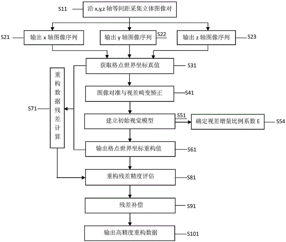
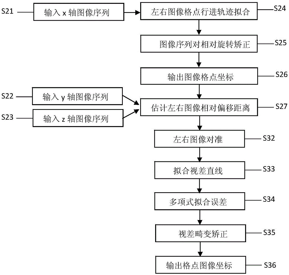
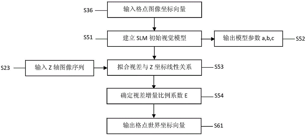
[0026] The present invention is described in further detail now in conjunction with accompanying drawing. figure 1 Show the flow chart of the SLM micro-visual data reconstruction method using residual feedback involved in the present invention, as shown in the figure, the SLM micro-visual data reconstruction method using residual feedback includes the following steps:

[0027] 1. Equidistant acquisition of SLM stereo image pairs

[0028] Make a grid-like plane calibration template by MEMS technology, design a circular pattern with 7 rows x 7 columns, the diameter is 0.15mm, the circular spacing of adjacent logo patterns is 0.3mm, and the positioning accuracy of the array grid points is ±0.25μm , the center point of the circular pattern is defined as the grid point. Fix the calibration template on the driving device, and the image acquisition plane is basically located at the focal plane of the SLM. The SLM has an effective depth range centered on the focal plane. The effectiv...


PUM


Abstract

The invention relates to an SLM microscopic vision data reconstruction method by using residual feedback, in particular, a method for improving SLM microscopic vision system reconstruction precision based on a pinhole camera model by using residual analysis to improve a residual compensation model. The method mainly comprises the following steps of: equal-interval SLM stereo image pair acquisition; image alignment and parallax distortion correction; initial visual model establishment; reconstruction residual calculation; reconstruction residual precision evaluation; and residual compensation. According to the method of the invention, based on the advantages of a pinhole camera model, a residual compensation model is established, a plurality of kinds of errors in a data reconstruction process of an SLM vision system are compensated, and therefore, parameter calibration difficulty can be decreased, and defects in the application of existing pinhole models to the micro optical field can be eliminated, and the novel model has high practicability. With the method of the invention adopted, as for any kind of SLM vision system, high-precision reconstruction data can be outputted as long as a residual compensation model is determined.

Description

Technical field: [0001] The invention relates to a method for reconstructing SLM microscopic vision data using residual feedback, in particular to improving the reconstruction accuracy of SLM microscopic vision system by establishing a residual compensation model based on a pinhole camera model and improving it method. Background technique: [0002] Optical stereo microscope is a kind of precision optical instrument, mainly divided into CMO type SLM (stereolight system), Greenough type SLM. The two sets of sub-optical paths of the CMO SLM share the large front-end objective lens, which contains three optical axes and are parallel to each other. Installing a CCD camera at the image plane of the sub-optical path of the CMO type SLM can constitute an SLM microscopic stereoscopic vision system. The SLM microscopic vision system is a typical computer binocular stereoscopic vision system, has a large working space, and is a non-contact optical system. For measurement, the camera...

Claims


Application Information

Patent Timeline
Patent Type & Authority Applications(China)
IPC IPC(8): G06T15/00
CPCG06T15/005
Inventor 王跃宗王军帅赵志忠
Owner BEIJING UNIV OF TECH
Learn More