Pilot-Operated Pressure Relief Valve with Lateral Pressure Connection

A pressure, valve body technology for the field of pre-controlled pressure limiting valves with lateral pressure connections

Active Publication Date: 2016-04-06
ROBERT BOSCH GMBH
View PDF5 Cites 1 Cited by
  • Summary
  • Abstract
  • Description
  • Claims
  • Application Information

AI Technical Summary

Problems solved by technology

This valve has no pre-control mechanism

Method used


Image

  • Pilot-Operated Pressure Relief Valve with Lateral Pressure Connection
  • Pilot-Operated Pressure Relief Valve with Lateral Pressure Connection
  • Pilot-Operated Pressure Relief Valve with Lateral Pressure Connection

Examples


Embodiment Construction

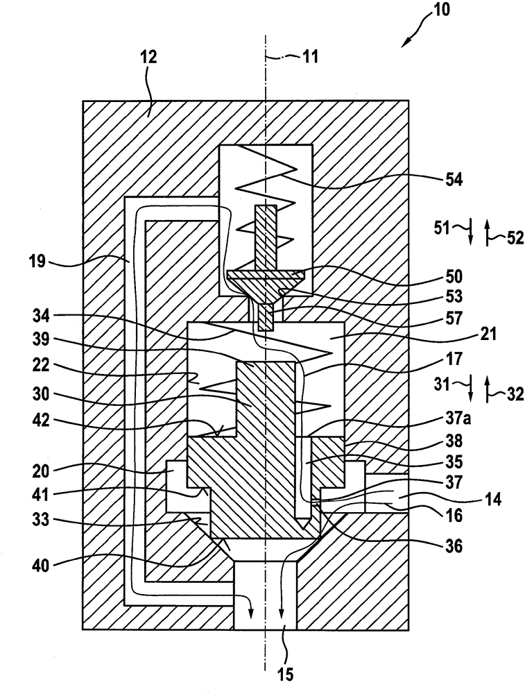
[0062] figure 1A roughly schematic sectional view of a valve 10 according to a first embodiment of the invention is shown. The valve 10 has a housing 12 in which a first valve body 30 is accommodated so as to be movable along a longitudinal axis 11 . In this case, the first valve body 30 is guided with little play in the cylindrical piston bore 22 with respect to the longitudinal axis 11 . Assigned to first valve body 30 is a first valve seat 33 , which is configured conically with respect to longitudinal axis 11 . The first valve body 30 is designed in the manner of a stepped piston, wherein the first valve body can seal off the first valve seat 33 with its smaller end face 40 in a sealing manner.

[0063] The second connection point 15 is arranged on the end face with respect to the longitudinal axis 11 relative to the first valve body 30 . The second connection point 15 is formed by a cylindrical bore with respect to the longitudinal axis 11 , which opens into the first ...


PUM


Abstract

A valve includes a housing, in which a first valve body is accommodated so that it is moveable in a direction of a longitudinal axis, a first valve seat configured to be closed by the first valve body and arranged on the housing, a first fluid flow path extending from a first connection via the first valve seat to a second connection, a second valve seat closeable by a moveable second valve body, the second valve body formed separately from the first valve body, a second fluid flow path extending from the first connection via a bypass duct in the first valve body, onwards via the second valve seat to the second connection, so that pressure at the first connection is limited upwardly by the first and the second valve body in that hydraulic fluid is led to the second connection via the first fluid flow path.

Description

technical field [0001] The invention relates to a valve according to the preamble of independent claim 1 . Background technique [0002] A valve is disclosed from a data page that can be retrieved on 24.07.2014 on the Internet under the address: http: / / www.boschrexroth.com / RDSearch / rd / r_64602 / rd64602_2013-02.pdf. This valve is a pilot-controlled pressure-limiting valve with feed-in function, which is designed as an in-line valve. The valve has a housing, which is also referred to as a bushing. A first valve body, also referred to as a piston, is accommodated in the housing in a movable manner about the longitudinal axis. A first valve seat, which can be closed by a first valve body, is arranged on the housing. A first fluid flow path extends from a first connection point through the first valve seat to a second connection point. Furthermore, a pilot control is provided which has a second valve seat which can be closed off by a second movable valve body. The second valve...

Claims


Application Information

Patent Timeline
Patent Type & Authority Applications(China)
IPC IPC(8): F16K31/363
CPCF16K17/105F16K31/363
Inventor R.诺伊鲍尔L.蔡泽T.希尔施L.格拉夫H.哈恩K.施奈德D.沃尔夫
Owner ROBERT BOSCH GMBH
Why Eureka
Try Eureka