Safe lifting appliance

A technology for safe lifting and equipment, applied in the direction of lifting devices, etc., can solve problems such as low safety, high cost, and cable fall, and achieve the effects of wide application range, simple mechanism, and convenient installation

Active Publication Date: 2016-04-06
SHANDONG MINGYUAN INTELLIGENT EQUIP TECH CO LTD
View PDF4 Cites 6 Cited by
  • Summary
  • Abstract
  • Description
  • Claims
  • Application Information

AI Technical Summary

Problems solved by technology

Civilian elevators have high requirements for supporting facilities, and generally cannot be used for outdoor operations; cables are used for lifting, and cable breakage is prone to fall accidents. In addition, power failure during operation is not conducive to escape
Construction elevators are suitable for outdoor use, but steel pipe supports need to be erected. The construction is relatively complicated and the cost is high. At the same time, construction elevators are lifted by cables, and the cable breaks are prone to fall accidents, and the safety is not high.
In addition, if there is a power outage, it is not conducive to rescue at high altitudes, and it does not have the functions of crisis relief and escape
[0004] Due to the different outdoor operation scenarios, for example, in the field of electric power construction, it is necessary to use lifting and climbing equipment to work on high electric towers. Inconvenient; such as a fire scene, the normal channel is blocked, and there is no effective lifting equipment to assist rescue work; therefore, designing a safe lifting equipment with high safety, wide application range, and crisis relief and escape functions is an urgent breakthrough in the industry. problem

Method used


Image

  • Safe lifting appliance
  • Safe lifting appliance
  • Safe lifting appliance

Examples


Embodiment Construction

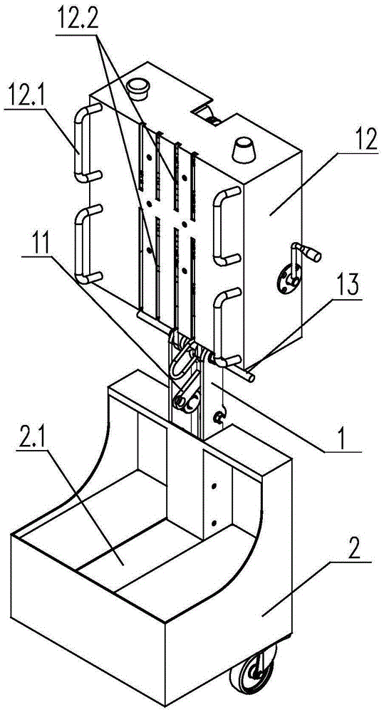
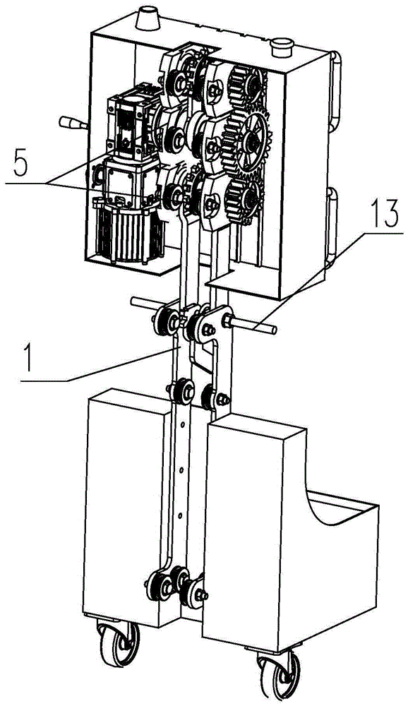
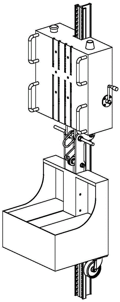
[0027] refer to Figure 1-Figure 8 A safety lifting device is shown, including a mounting frame 1, and a carrier 2, a power component 3, a lifting component 4 and an electric control component are arranged on the mounting frame 1, and the power component 3 and the lifting component 4 are in the same direction as the carrier 2 Linkage, the carrier 2 is provided with a battery containing groove 2.1. The electric control component is electrically connected with the power component 3, and the power component 3 drives the lifting component 4 to move up and down; the lifting component 4 includes a driving part 4.1 connected as one, an upper driven climbing part 4.2 and a lower driven climbing part 4.3, the backs of the driving part 4.1, the upper driven climbing part 4.2 and the lower driven climbing part 4.3 are all hinged with limited rolling parts 5; the upper driven climbing part 4.2 and the lower driven climbing part 4.3 are equipped with Climbing sprocket 6; the driving part ...


PUM


Abstract

The invention relates to a safe lifting appliance and belongs to the technical field of lifting equipment, comprising a mounting rack, a carrier, a power assembly, a lifting assembly and an electric control assembly, wherein the power assembly and the lifting assembly achieve isodirectional linkage with the carrier; the electric control assembly is electrically connected with the power assembly; the power assembly drives the lifting assembly to move up and down; the lifting assembly comprises a driving part, an upper driven climbing part and a lower driven climbing part which are connected into a whole; the back surfaces of the driving part, the upper driven climbing part and the lower driven climbing part are all hinged with a limiting rolling part; climbing chain wheels are arranged on both the upper driven climbing part and the lower driven climbing part; the driving part is located between the upper driven climbing part and the lower driven climbing part and drives the climbing chain wheels on the upper driven climbing part and the lower driven climbing part to rotate; the electric control assembly comprises a program control panel and a switch handle; and the switch is used for controlling the operation of the power assembly. The safe lifting appliance has the advantages of being high in safety and wide in application scope and having functions of solving crises and escaping.

Description

technical field [0001] The invention belongs to the technical field of lifting equipment, and in particular relates to a safe lifting equipment with high safety, wide application range, crisis relief and escape functions; it can be used as outdoor construction climbing equipment, high-rise rescue (escape) equipment, fire escape ladder , the safe passage of old houses, and the use of elevators for people. Background technique [0002] Lifting equipment is a device that enables people or things to move back and forth between low and high places. The important indicators of lifting equipment are: 1. Safety; 2. Detachability; 3. Has the function of crisis relief and escape. [0003] At present, the common lifting mechanisms include civil elevators and building elevators. Civilian elevators have high requirements for supporting facilities, and generally cannot be used for outdoor operations; cables are used for lifting, and cable breakage is prone to fall accidents. In addition,...

Claims


Application Information

Patent Timeline
Patent Type & Authority Applications(China)
IPC IPC(8): B66F11/00
CPCB66F11/00B66F2700/09
Inventor 吕伟宏赖建防尤双星缪学勤孙飞
Owner SHANDONG MINGYUAN INTELLIGENT EQUIP TECH CO LTD
Why Eureka
Try Eureka