Auxiliary line discharging machine

A technology of off-line machine and driving mechanism, which is applied in the direction of conveyors, mechanical conveyors, conveyor objects, etc., can solve the problem of low unloading efficiency, achieve the effect of improving unloading efficiency and reducing wear

Active Publication Date: 2016-04-06
TCL KING ELECTRICAL APPLIANCES HUIZHOU
View PDF5 Cites 4 Cited by
  • Summary
  • Abstract
  • Description
  • Claims
  • Application Information

AI Technical Summary

Problems solved by technology

[0004] The main purpose of the present invention is to provide an auxiliary off-line machine, aiming at solving the technical problems of low unloading efficiency and reducing wear during the off-line process

Method used


Image

  • Auxiliary line discharging machine
  • Auxiliary line discharging machine
  • Auxiliary line discharging machine

Examples


Embodiment Construction

[0034] It should be understood that the specific embodiments described here are only used to explain the present invention, not to limit the present invention.

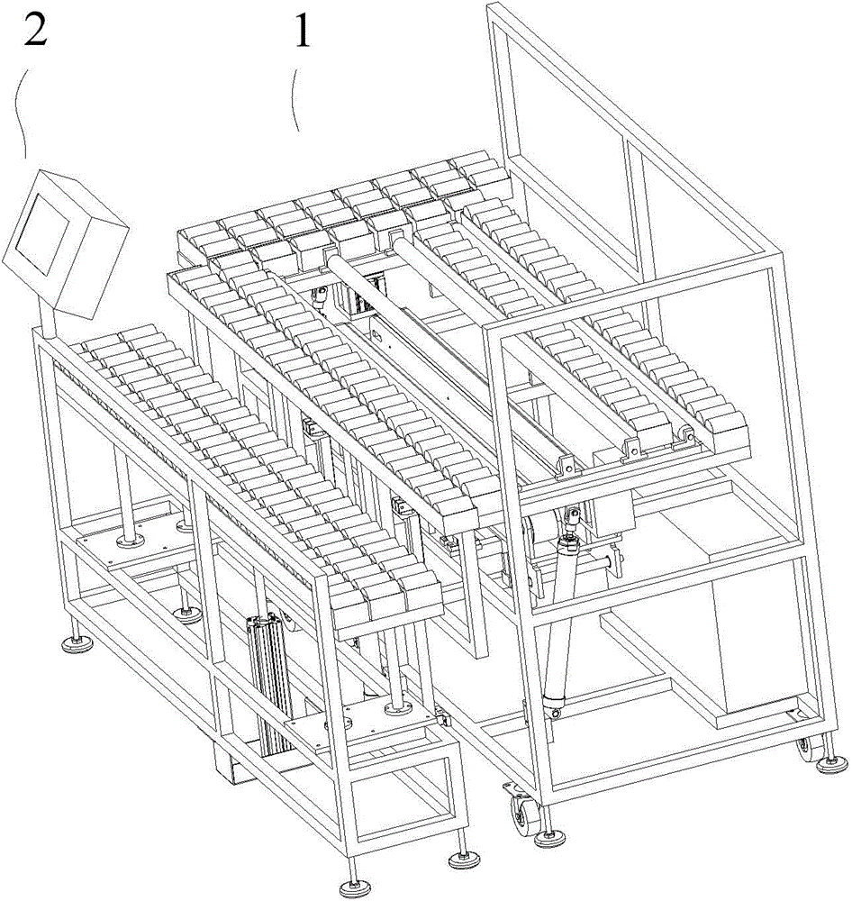
[0035] The invention provides an auxiliary off-line machine, such as figure 1 As shown, the auxiliary offline machine includes an overturning unloading device 1 and a unloading supporting device 2 .

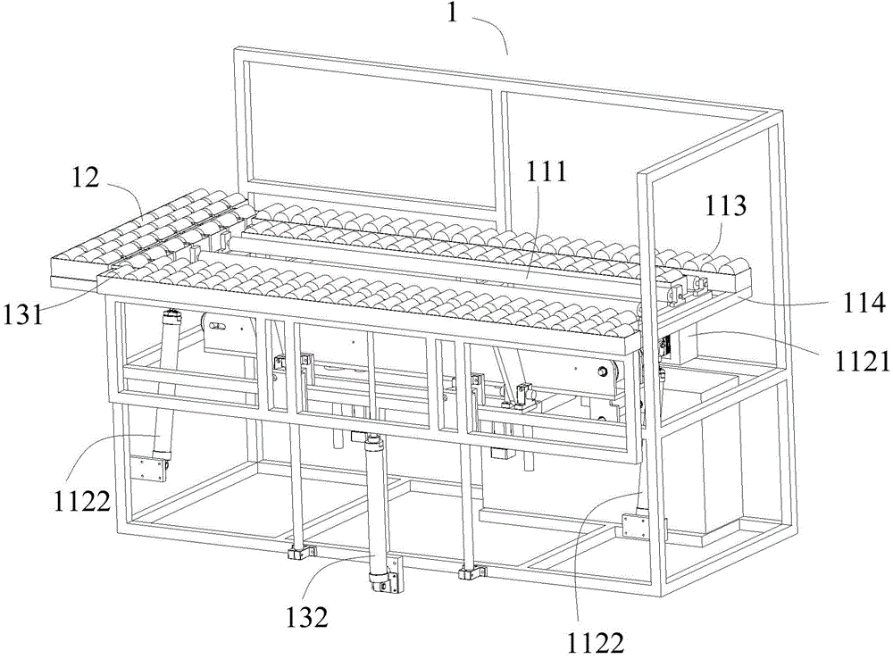
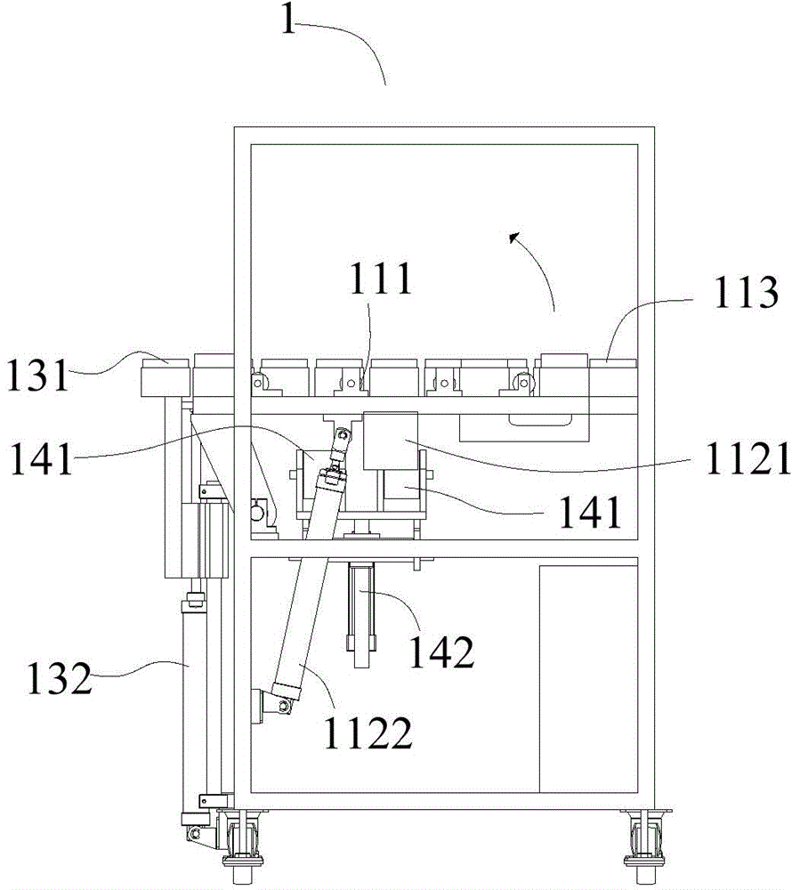
[0036] Such as Figure 2 to Figure 4 shown, where Figure 4 Some parts that have little relationship with the present invention are hidden in order to show the structure of the present invention more clearly. The turning and unloading device 1 includes a turning drive mechanism and a turning supporting roller 111, and the axial direction of the turning supporting roller 111 is consistent with the discharge The direction is perpendicular to each other, and the overturning supporting roller 111 can rotate around its roller shaft. There are more than two overturning supporting rollers 111 and they together form an overtur...


PUM


Abstract

The invention discloses an auxiliary line discharging machine capable of being matched with an assembly line. The auxiliary line discharging machine comprises an overturn discharging device. The auxiliary line discharging machine is characterized in that the overturn discharging device comprises an overturn driving mechanism and overturn supporting rollers; the axial direction of the overturn supporting rollers is perpendicular to the discharging direction; the overturn supporting rollers can rotate around rolling shafts of the overturn supporting rollers; two or more together-formed overturn supporting faces used for supporting materials are arranged on the overturn supporting rollers; during discharging, the overturn driving mechanism drives the overturn supporting rollers so as to make the overturn supporting faces incline towards one side and the materials slide down along the overturn supporting faces under the action of the gravity to achieve discharging. According to the auxiliary line discharging machine, the technical problems of low discharging efficiency and abrasion in the line discharging process are solved.

Description

technical field [0001] The invention relates to an auxiliary off-line machine that can be matched with an assembly line. Background technique [0002] The auxiliary off-line machine in the prior art includes a turning device and a supporting device. The supporting device is located on one side of the turning device. The turning device includes a bracket, a turning platform, a telescopic mechanism, a belt conveyor and a belt conveyor lifting mechanism, and the turning platform on the displacement bracket. When in use, after the electronic product enters the auxiliary off-line machine, the electronic product is transported to the predetermined position by the belt conveyor. After the electronic product is in place, the belt conveyor stops and sinks, and the turning platform is ready to turn over. After the turning platform receives the turning signal and executes Flip, the flip platform is tilted to the side of the supporting device, flipped to the tilted state, the electroni...

Claims


Application Information

Patent Timeline
Patent Type & Authority Applications(China)
IPC IPC(8): B65G47/34B65G37/00
CPCB65G47/22B65G47/34
Inventor 庄子开胡凌飞李竞帆
Owner TCL KING ELECTRICAL APPLIANCES HUIZHOU
Why Eureka
Try Eureka