Printing device of circular bending die and using method for printing device

A technology of circular pressing and printing, applied in the field of printing devices of circular pressing die, can solve the problems of low energy utilization rate and poor work efficiency, and achieve the effects of high energy utilization rate, improved printing quality and strong synchronization

Inactive Publication Date: 2016-04-06
WUHAN TEXTILE UNIV
View PDF7 Cites 0 Cited by
  • Summary
  • Abstract
  • Description
  • Claims
  • Application Information

AI Technical Summary

Problems solved by technology

[0005] The purpose of the present invention is to overcome the defects and problems of low energy utilization rate and poor work efficiency in the prior art, and provide a printing device and its Instructions

Method used


Image

  • Printing device of circular bending die and using method for printing device
  • Printing device of circular bending die and using method for printing device
  • Printing device of circular bending die and using method for printing device

Examples


Embodiment 1

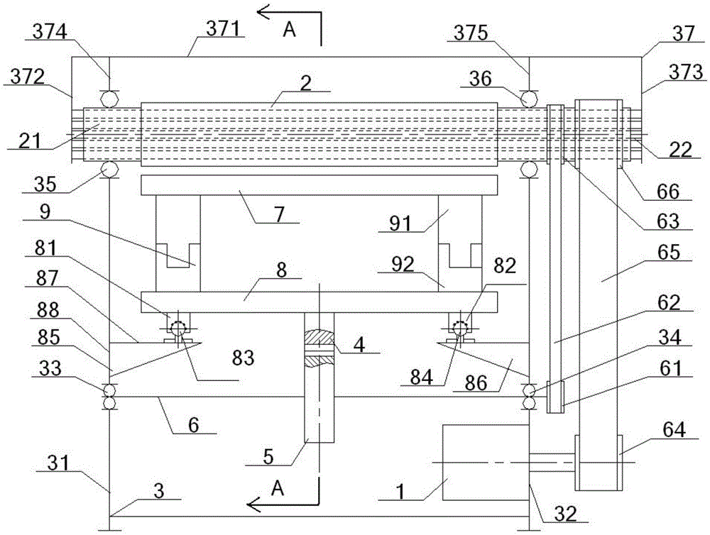
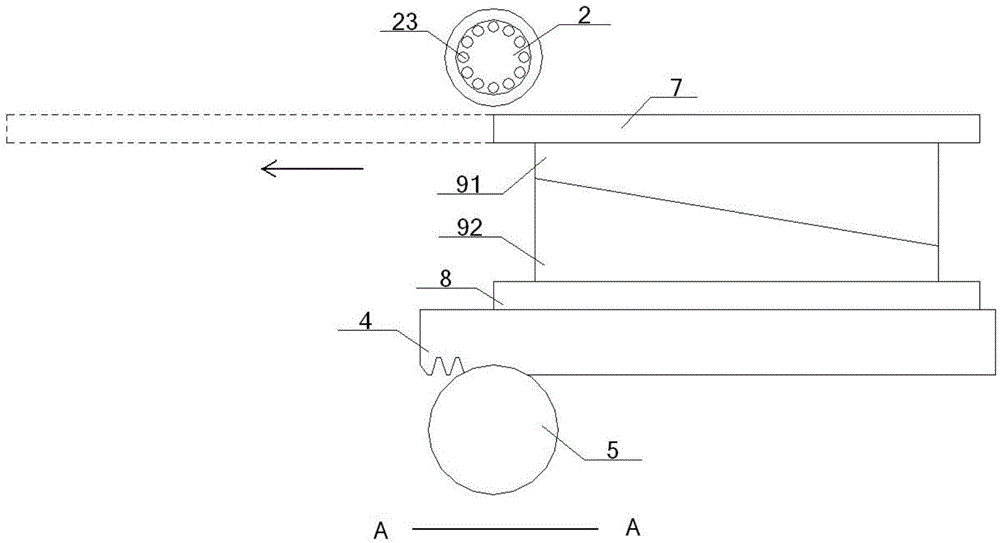
[0052] see figure 1 – Figure 4 , a printing device for a circular die, comprising a cylinder 2, a stand 3, a rack 4, a gear 5, a transmission shaft 6, and a printing table 7, and the stand 3 includes a left side frame 31 and a right side frame parallel to each other. Frame 32, the middle part and the top of the left side frame 31 are respectively provided with a middle left bearing group 33 and a top left bearing group 35, and the middle part and top of the right side frame 32 are respectively provided with a middle right bearing group 34 and a top right bearing group 36, and The middle left bearing group 33 and the middle right bearing group 34 are arranged coaxially, the top left bearing group 35 and the top right bearing group 36 are arranged coaxially;

[0053]The middle left bearing group 33 is in rolling fit with the left end of the transmission shaft 6 inserted into it, the middle right bearing group 34 is in rolling fit with the right end of the transmission shaft 6...

Embodiment 2

[0057] Basic content is the same as embodiment 1, the difference is:

[0058] The bottom surface of the left linear guide rail 83 is fixedly connected with the left side frame 31 through the left fixed block 85, and the left fixed block 85 is set higher than the middle left bearing group 33; the bottom surface of the right linear guide rail 84 passes through the right fixed block 86 and the right side Frame 32 is fixedly connected, and right fixed block 86 is higher than middle right bearing group 34 and is arranged. The cross-sections of the left fixed block 85 and the right fixed block 86 are triangular structures, the long horizontal side 87 of the triangular structure is connected with the bottom surface of the left linear guide rail 83 or the right linear guide rail 84, and the short vertical side 88 of the triangular structure Connect with the left frame 31 or the right frame 32.

Embodiment 3

[0060] Basic content is the same as embodiment 1, the difference is:

[0061] The driving motor 1 is connected with the right side frame 32 , and the driving end of the driving motor 1 passes through the right side frame 32 and is connected with the inside of the outer driving wheel 64 . The drive motor 1 is an asynchronous motor. A plurality of heating pipes 23 are arranged inside the drum 2 along its inner wall.


PUM


Abstract

The invention discloses a printing device of a circular bending die. The printing device comprises a roller, a printing table board and inner and outer sets of transmission mechanisms, wherein the outer transmission mechanism, namely an outer drive wheel, an outer synchronous belt, an outer synchronous wheel, is responsible for introducing outer energy resources and driving the roller to rotate; the inner transmission mechanism, namely an inner drive wheel, an inner synchronous belt and an inner synchronous wheel, is responsible for driving the printing table board to horizontally move below the roller by virtue of a transmission shaft, a gear, a rack, a fixed plate and a transition part; the transition part comprises two wedge block sets perpendicularly connected to the printing table board and the fixed plate; each wedge block set comprises an upper wedge block and a lower wedge block which are right-trapezoid-shaped structures; and the upper wedge block and the lower edge block relatively slide, so that the height of the printing table board can be regulated. The printing device is relatively high in energy resource utilization rate, is relatively good in working efficiency, is relatively strong in adjustability and is relatively wide in scope of application.

Description

technical field [0001] The invention relates to a printing device, in particular to a printing device for a circular press die and a method for using the same, which is particularly suitable for improving the working efficiency and increasing the adjustability during printing. Background technique [0002] At present, with the development of the economy, the demand for various printing products is also increasing. The printing of commonly used textiles includes flat screen printing , Rotary screen printing , roller printing , transfer printing and inkjet printing . in, roller printing It refers to the process of printing on the fabric with a cylinder engraved with a concave pattern, also known as copper roller printing. When printing, first stain the surface of the cylinder with color paste, and then use a sharp and flat scraper to scrape off the color paste on the surface of the unengraved part of the cylinder, so that the color paste remains in the concave patte...

Claims


Application Information

Patent Timeline
IPC IPC(8): B41F17/38B41M1/10B41M1/26
CPCB41F17/003B41F17/38B41M1/10B41M1/26
Inventor 张智明刘芳余联庆殷先泽祖耀赵逸轩孙俊
Owner WUHAN TEXTILE UNIV
Why Eureka
Try Eureka