Thread driven die equipment

A thread transmission and mold technology, which is applied in the field of mold manufacturing, can solve the problems of thread fit influence, precision degree affecting equipment operation accuracy and transmission efficiency, etc.

Inactive Publication Date: 2016-04-06
余苏祥
View PDF5 Cites 1 Cited by
  • Summary
  • Abstract
  • Description
  • Claims
  • Application Information

AI Technical Summary

Problems solved by technology

[0004] However, since the precision of the thread fit affects the running accuracy and transmission efficiency of the equipment, when the movable m...

Method used


Image

  • Thread driven die equipment
  • Thread driven die equipment
  • Thread driven die equipment

Examples


Embodiment Construction

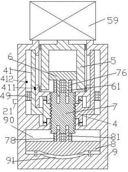
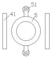
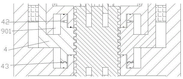
[0011] Combine below Figure 1-3 Embodiments of the present invention will be described.

[0012] refer to Figure 1-3 , according to the embodiment of the screw drive mold equipment, including a frame 9, opposite to the die 91 arranged at the bottom of the frame 9 and fixed in the bottom cavity 90 of the frame 9 in the circumferential direction and axially The movable punch 8 movable upwards and the connecting bearing column 7, the lower end of the connecting bearing column 7 is connected with the movable punch 8 through the lower elastic connector 78, and the movable punch 8 passes through A plurality of punch extensions 81 that are fixedly arranged on the upper surface and slidably extend into the connecting bearing column 7 are fixed with the connecting bearing column 7 in the circumferential direction; The connecting piece 76 is connected with the threaded block 6 threadedly fitted in the threaded sleeve 5, and the threaded block 6 is fixedly arranged on the lower surfa...


PUM


Abstract

The invention discloses thread driven mold equipment which comprises a machine frame (9), a movable male die (8) and a connecting bearing column (7). The movable male die (8) is opposite to a female die (91) arranged at the bottom of the machine frame (9), and is fixed in the circumferential direction and movable in the axial direction in an inner cavity (90) at the bottom of the machine frame (9). The lower end of the connecting bearing column (7) is connected with the movable male die (8) through a lower elastic connecting piece (78). The movable male die (8) and the connecting bearing column (7) are fixed in the circumferential direction due to the fact that the upper surface of the movable male die (8) is fixedly provided with a plurality of male die extending portions (81) capable of extending into the connecting bearing column (7) in a slidable mode. The upper end of the connecting bearing column (7) is connected with a threaded block (6) through an upper elastic connecting piece (76), wherein the threaded block (6) is arranged in a threaded casing pipe (5) in a threaded fit mode.

Description

technical field [0001] The invention relates to the field of mold manufacturing, in particular to a screw drive mold equipment. Background technique [0002] In the mold device, some mold pressing mechanisms are often used to drive the movable mold. The driving method often has a hydraulic type and a threaded type. For small-scale molding processing, screw-type driving and pressing can have the advantages of cost reduction and easy maintenance. [0003] The thread fit itself is self-locking, so the pressing down method of this mode can well bear the gravity of the dynamic model and other loads, and make the overall equipment have good stability. [0004] However, since the precision of the thread fit affects the running accuracy and transmission efficiency of the equipment, when the movable mold is subjected to an unexpected impact from the outside, it is easy to transmit the impact load to the thread fit part, which will affect the thread fit. This is especially true dur...

Claims


Application Information

Patent Timeline
IPC IPC(8): B21D37/10
CPCB21D37/10
Inventor 余苏祥
Owner 余苏祥
Why Eureka
Try Eureka