Stripper unit and hydraulic working apparatus having a stripper unit

A technology of operating equipment and scrapers, applied in the field of hydraulic cylinders and hydraulic operating equipment, can solve the problem that the scraper unit no longer performs cleaning and/or protection functions

Active Publication Date: 2016-03-30
DR WALTER HUNGER BET GMBH & CO BESITZ
View PDF10 Cites 6 Cited by
  • Summary
  • Abstract
  • Description
  • Claims
  • Application Information

AI Technical Summary

Problems solved by technology

[0004] However, applications are also known in which conventional wiper units can reach their capacity limit and no longer perform an adequate cleaning and / or protective function

Method used


Image

  • Stripper unit and hydraulic working apparatus having a stripper unit
  • Stripper unit and hydraulic working apparatus having a stripper unit
  • Stripper unit and hydraulic working apparatus having a stripper unit

Examples


Embodiment Construction

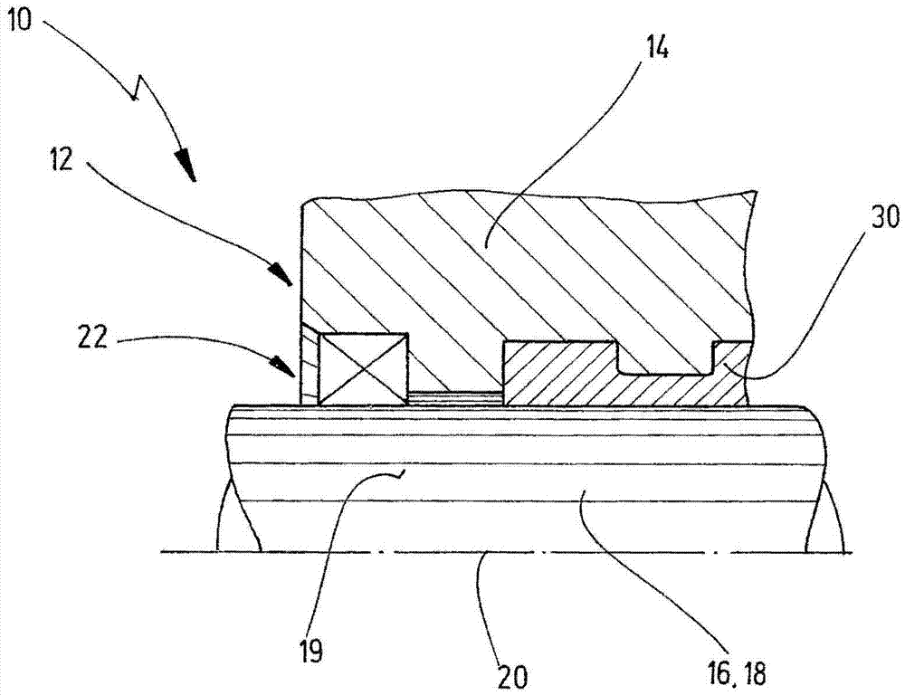
[0036] figure 1 A partial side view of a hydraulic working device 10 is shown, which can be designed, for example, as a hydraulic cylinder. The hydraulic working device 10 has a housing-fixed part or housing part 14 which surrounds a sliding counterpart 16 . Sliding counterpart 16 is designed here, for example, as piston rod 18 (in figure 1 are only partially shown). The sliding counterpart 16 has a substantially rotationally symmetrical, in particular cylindrical, sliding surface 19 . The sliding counterpart 16 also has a longitudinal axis 20 which can coincide with a corresponding longitudinal axis passing through the housing part 14 . The hydraulic working device 10 can be designed to generate a relative movement, in particular a sliding movement along the longitudinal axis 20 , between the housing part 14 and the sliding counterpart 16 . In this case, it is initially irrelevant which of the two parts 14 , 16 performs the absolute movement.

[0037] The hydraulic worki...


PUM


Abstract

The invention relates to a stripper unit (44) and to a hydraulic working apparatus (40) having a stripper unit (44). The stripper unit is formed in particular as an ice stripper for hydraulic working apparatuses for protecting a secondary side (54) against environmental influences which arise on a primary side (52), in particular for protecting guide arrangements and/or sealing arrangements (42), and is provided with a holding ring (46), which is formed in a substantially rotationally symmetrical manner about a longitudinal axis (20) and has a contact portion (58) for reception on a housing part (14), with a primary stripper (48), in particular an outer stripper, and with a secondary stripper (50), which is offset axially in the direction of the secondary side (54) in relation to the primary stripper (48), wherein a primary lip (74) is formed on the primary stripper (48) and a secondary lip (88) is formed on the secondary stripper (50), wherein the primary lip (74) and the secondary lip (88), when in a joined state, make sealing contact with a sliding surface (19) of a guided sliding partner part (16), in particular a piston rod, wherein the primary lip (74) protrudes like a collar in the direction of the primary side (52) and, on the side thereof which is remote from the guided sliding partner part (16) when in a joined state, tapers conically at least in certain portions in the direction of the primary side (52), and wherein the primary lip (74) has a contact surface (76) designed to bear against the sliding surface (19).

Description

technical field [0001] The invention relates to a scraper unit, in particular an ice scraper for hydraulic working equipment, for protecting the secondary side from environmental influences occurring on the primary side, in particular for protecting guide structures and / or seals structure, the wiper unit has a retaining ring, a primary wiper and a secondary wiper. The invention also relates to a hydraulic working device, in particular a hydraulic cylinder, having such a scraper unit. Background technique [0002] Common types of wiper units (also called wipers), for example also called dirt wipers, ice scrapers, etc., are known in the prior art and are used in a large number of cylinder-piston structures that are exposed to the external environment. Conventional wipers are used, for example, in hydraulic and / or pneumatic devices such as vehicle crash bumpers, in which, for example, a piston rod is moved relative to a housing. In this case, parts of the piston rod are usual...

Claims


Application Information

Patent Timeline
Patent Type & Authority Applications(China)
IPC IPC(8): F15B15/14F16J15/56F16J15/16F16J15/3232
CPCF15B15/1461F16J15/166F16J15/3232F16J15/56A47L11/4069
Inventor 英格里德·泓格
Owner DR WALTER HUNGER BET GMBH & CO BESITZ
Why Eureka
Try Eureka