
Substrate processing apparatus and substrate processing method

A technology for a substrate processing apparatus and a substrate processing method, which are applied in the directions of cleaning methods and utensils, chemical instruments and methods, and cleaning methods using liquids, etc., can solve the problems of etching residues, large etching residues, and etching liquid 351 without stirring. , to achieve the effect of preventing the fluctuation of the processing rate and suppressing the fluctuation of the temperature

Active Publication Date: 2016-03-30
DAINIPPON SCREEN MTG CO LTD
View PDF6 Cites 9 Cited by
  • Summary
  • Abstract
  • Description
  • Claims
  • Application Information

AI Technical Summary

Problems solved by technology

Conversely, if the landing position of the jet stream 361 of the liquid droplet of the etching liquid is very far away from the landing position of the continuous flow 362 of the etching liquid, the liquid splash 370 will not occur. The etchant is stirred, so there is a problem of creating a large amount of etch residue
[0013] In addition, in the case where the above-mentioned etching method is realized using the device configuration of the modified example of Patent Document 1, a groove (groove formed in a pattern of the substrate) T1 depressed in the vertical direction is formed on the upper surface of the substrate W. , in the case of processing the film U1 formed in the trench T1, as Figure 15 As shown, the etching solution 351 formed in the vicinity of one side wall of the trench T1 formed on the substrate W is not sufficiently stirred due to the jet stream 361 that sprays the liquid droplets of the etching solution obliquely.
Therefore, there is a problem that the gas bubbles 99 stay on one side wall to generate etching residues.

Method used


Image

  • Substrate processing apparatus and substrate processing method
  • Substrate processing apparatus and substrate processing method
  • Substrate processing apparatus and substrate processing method

Examples


Embodiment Construction

[0055] Hereinafter, embodiments of the present invention will be described based on the drawings. In the drawings, parts having the same structure and function are given the same reference numerals, and repeated descriptions will be omitted in the following description. In addition, each drawing is schematically shown. In addition, in the description of the embodiment, the vertical direction is the vertical direction, the substrate W side is the upper side, and the spin chuck 111 side is the lower side.

[0056]

[0057]

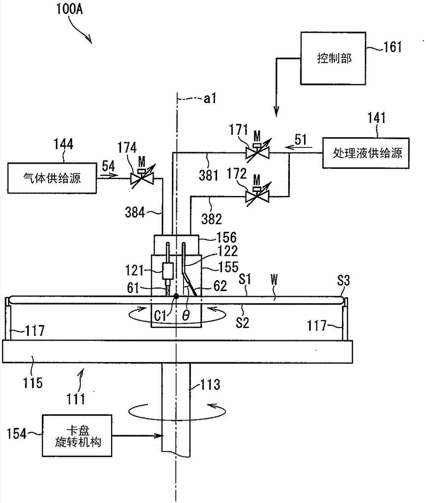
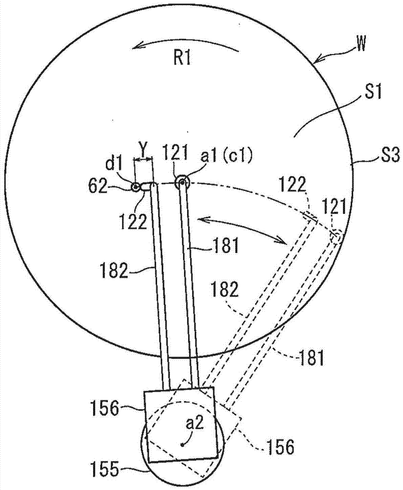
[0058] figure 1 It is a figure which schematically shows an example of the schematic structure of 100 A of substrate processing apparatuses concerning embodiment. figure 2 It is a figure which looked at the two nozzles 121 and 122 of the substrate processing apparatus 100A from above the board|substrate W.

[0059] The substrate processing apparatus 100A processes a substrate using a processing liquid. Specifically, for example, the substrate proce...


PUM


Abstract

The invention relates to a substrate processing apparatus and a substrate processing method, being able to restrain production of residue and splashing of liquid. The substrate processing apparatus includes a rotating holder for a substrate, a first nozzle used to eject a jet flow, a second nozzle used to discharge a continuous flow, and a nozzle moving unit integrally moving the first and second nozzles. A landing position of the continuous flow is located closer to a rotation center than a landing position of the jet flow is. At least movement paths of the landing positions of the jet flow and the continuous flow or flow directions of the continuous flow and the jet flow are different from each other. The movement paths are made to be different from each other by locating the landing position of the continuous flow downstream of the movement path of the landing position of the jet flow. The flow directions are made to be different from each other by tilting the continuous flow.

Description

technical field [0001] The present invention relates to a substrate processing technique for processing a substrate by supplying a processing liquid to the substrate while rotating the substrate. Substrates to be processed include semiconductor wafers, glass substrates for liquid crystal display devices, glass substrates for plasma display panels, optical disk substrates, magnetic disk substrates, magneto-optical disk substrates, and photomask substrates. Background technique [0002] In the manufacturing process of such a substrate, for example, Patent Documents 1 and 2 disclose an apparatus for processing a substrate as follows. This apparatus for processing a substrate includes a two-fluid nozzle and a nozzle (also referred to as a "straight nozzle") that ejects a continuous flow of a processing liquid onto a substrate. The two-fluid nozzle mixes a processing liquid with a pressurized gas to generate a jet flow of liquid droplets of the processing liquid, and ejects the ...

Claims


Application Information

Patent Timeline
Patent Type & Authority Applications(China)
IPC IPC(8): H01L21/02H01L21/67
CPCH01L21/02052H01L21/67023H01L21/67051B08B3/024H01L21/30604H01L21/6715H01L21/67017H01L21/6704B08B3/04B08B3/02B08B1/32
Inventor 藤原直澄江户彻菅原雄二阿野诚士泽岛隼
Owner DAINIPPON SCREEN MTG CO LTD
Learn More