


Quick Research
Generate reliable direction feasibility study reports for your R&D in just a few steps.

Technical Q&A
Discover and master advanced knowledge NOW. Basics, ideas, possibilities, all at once.

Find Solutions
As an expert in R&D theories, this can generate solutions to your technical problems instantly.

Evaluate Feasibility
Analyze your overall solution with one click, know your potential R&D risks in advance.

Monitor Landscape
Get weekly tech updates, stay abreast of the latest tech innovations and key insights.
discharge lamp
A technology for discharge lamps and discharge tubes, which is applied in the manufacture of discharge tubes/lamps, parts and circuits of gas discharge lamps, and can solve problems such as increased manufacturing costs, complex grain boundaries, and complex shapes at the front end of electrodes
- Summary
- Abstract
- Description
- Claims
- Application Information
AI Technical Summary
Problems solved by technology
Method used
Image

Examples
Embodiment 1
[0067] The discharge lamp of this embodiment is composed of a cathode, and two metal members are joined by SPS bonding. The cathode is made of thoriated tungsten as a front metal member and molybdenum as a rear metal member. In the SPS bonding apparatus, using an SPS apparatus manufactured by SPSSyntex Co., Ltd., a pressure of 45 MPa was applied from both sides of the metal member in a vacuum environment, and the sintering temperature near the bonding surface was maintained at 1500° C. for 10 minutes to perform solid phase bonding.
[0068] The axial length of the metal part on the front end is 3mm, the cathode diameter is 20mm, and the cathode is 42mm in total length. Modeling is performed, and the heat applied to the junction when the discharge lamp is lit is performed by a computer based on the heat assumed at the time of power 12.5kW. Simulation of stress near a face. As a result of the simulation, it was confirmed that during lighting of the discharge lamp, stress was con...
Embodiment 2
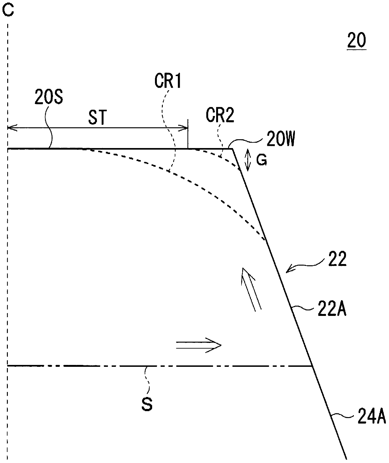
[0070] In Example 2, three types of cathodes were modeled in which the axial lengths of the metal parts on the tip side were 3mm, 5mm, and 7mm, and the temperature distribution when the discharge lamp was lit was reproduced, and the displacement of the tip of the electrode during lighting was calculated. amount (expansion). The amount of displacement here refers to the distance from the axis of the electrode (refer to image 3 The amount of change in shape of the label ST) (refer to image 3 label G). In addition, it is the same specification as the said Example 1 except the axial length of the front-end|tip side metal member. As a comparative example, a cathode (axial length: 42 mm) integrally formed of only tungsten without joining metal members was used.
[0071] Image 6 This is a graph of the displacement amount of the electrode tip.
[0072] Such as Image 6 As shown, it can be seen that the front end displacement (ratio) of the three kinds of cathodes in which the...
PUM
| Property | Measurement | Unit |
|---|---|---|
| length | aaaaa | aaaaa |
Abstract
Description
Claims
Application Information
 - R&D Engineer
- R&D Manager
- IP Professional
- Industry Leading Data Capabilities
- Powerful AI technology
- Patent DNA Extraction
Browse by: Latest US Patents, China's latest patents, Technical Efficacy Thesaurus, Application Domain, Technology Topic, Popular Technical Reports.
© 2024 PatSnap. All rights reserved.Legal|Privacy policy|Modern Slavery Act Transparency Statement|Sitemap|About US| Contact US: help@patsnap.com