Ultrasonic flowmeter

An ultrasonic and flowmeter technology, which is applied in the direction of measuring flow/mass flow, liquid/fluid solid measurement, measuring devices, etc., can solve problems such as easy to change the flow of people, the installation and maintenance of measurement originals, etc.

Inactive Publication Date: 2016-03-30
AUCMA
View PDF5 Cites 2 Cited by
  • Summary
  • Abstract
  • Description
  • Claims
  • Application Information

AI Technical Summary

Problems solved by technology

[0004] In the field of measurement of people flow in commercial cold chains, the main method is to install the measurement element at the place where the flow of people passes, and the data measured by the measurement element is transmitted to the controller for analysis to obtain the measurement results. The installation and maintenance of the measuring element are easily affected

Method used


Image

  • Ultrasonic flowmeter
  • Ultrasonic flowmeter

Examples


Embodiment Construction

[0014] The specific embodiment of the present invention will be further described below in conjunction with accompanying drawing and specific embodiment:

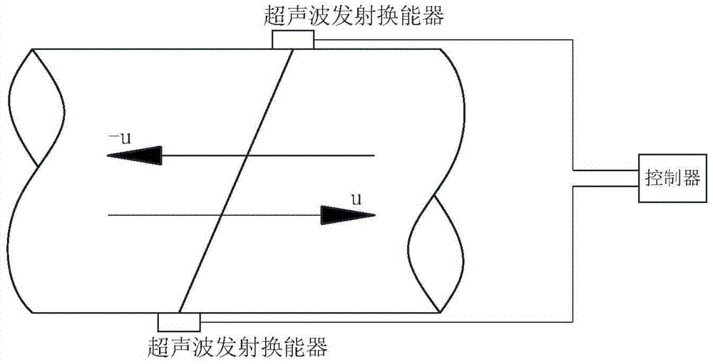
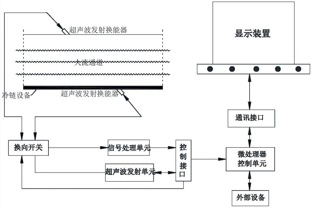
[0015] Such as Figure 1-2 As shown, an ultrasonic flowmeter includes an ultrasonic transmitting transducer and a receiver, piezoelectric elements are arranged in the ultrasonic transmitting transducer and the receiver, and the ultrasonic transmitting transducer is made of a piezoelectric material. The ultrasonic transmitting transducer is connected to the ultrasonic transmitting unit, and the receiver is connected to the signal processing unit. The signal processing unit includes a calculation instrument and a signal amplifier. The calculation instrument receives and processes the flow signal received by the receiver, and the signal amplifier amplifies the flow signal received by the receiver. The ultrasonic emitting unit and the signal processing unit are connected with a microprocessor control unit, and the microprocesso...


PUM


Abstract

The invention discloses an ultrasonic flowmeter, and particularly relates to the field of ultrasonic passenger flow volume collection devices. The defects that according to existing passenger flow volume measurement, a measuring element needs to be installed at a passenger passing position, and dynamic state of passenger flow is likely to be changed are overcome. The ultrasonic flowmeter comprises an ultrasonic transmitting transducer and a receiver. The ultrasonic transmitting transducer and the receiver are each provided with a piezoelectric element. The ultrasonic transmitting transducer is connected with an ultrasonic transmitting unit. The receiver is connected with a signal processing unit. The signal processing unit comprises a calculation instrument and a signal amplifier. The ultrasonic transmitting unit and the signal processing unit are connected with a microprocessor control unit. A display device is connected to the microprocessor control unit. The ultrasonic transmitting transducer is made of piezoelectric materials. The display device comprises a computer.

Description

technical field [0001] The invention relates to the field of ultrasonic passenger flow collection devices, in particular to an ultrasonic flowmeter. Background technique [0002] As early as the seventeenth century, people have begun to conduct flow tests on liquids. The development of flow test technology is not limited to liquid test. People have been able to master the test of gas flow proficiently, and there are countless test methods, such as propagation velocity difference method, beam offset method, Doppler method, spatial filtering method, etc. Most of the early flow testing equipment in our country was imported. Now we have accurately mastered this technology and quickly put it into production in the process industry, energy measurement, and urban public utilities, which also promotes the rapid development of flow meters. The rapid development of microelectronics technology and computer technology has greatly promoted the upgrading of flow meters, and new flow met...

Claims


Application Information

Patent Timeline
Patent Type & Authority Applications(China)
IPC IPC(8): G01F1/66
CPCG01F1/66
Inventor 徐玉峰张震德尹云东李莎莎刘宗岳
Owner AUCMA
Why Eureka
Try Eureka