Multilayer biofuel heating furnace

A biofuel and heating stove technology, applied in the field of multi-layer biofuel heating stoves, can solve problems such as affecting combustion, waste, and aggravating environmental pollution

Inactive Publication Date: 2016-03-30
CHONGQING HUAWANLUN BIOLOGICAL NEW ENERGY TECH CO LTD
View PDF6 Cites 2 Cited by
  • Summary
  • Abstract
  • Description
  • Claims
  • Application Information

AI Technical Summary

Problems solved by technology

Our country is a large agricultural country, and a large amount of straw is burned in the farmland every year, which not only aggravates the environmental pollution, such as the frequent occurrence of smog weather, but also wastes energy, the heat energy of the straw cannot be used, and the straw cannot be fully and effectively used. Utilization mainly lies in the electrification of rural life. People no longer rely on straw for cooking, so there is too much surplus. Straw is directly used in industrial production, and its energy per unit volume cannot meet its heat energy requirements. In order to make full use of straw For the above problems, our country vigorously advocates the remanufacturing of straw to meet the needs of industrial production. Now it is mainly crushed and pressed into high-density particles to increase the heat energy per unit volume. Extrusion technology is used in the existing technologies to form solid After the particles are piled up, the gap is small, and the airflow is not smooth after being filled into the boiler, which affects the combustion, and the accumulation of burnt ash also affects the combustion, which still needs to be solved by further innovation

Method used


Image

  • Multilayer biofuel heating furnace
  • Multilayer biofuel heating furnace

Examples


Embodiment Construction

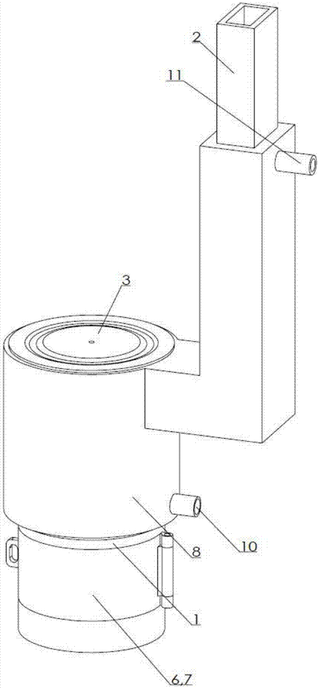
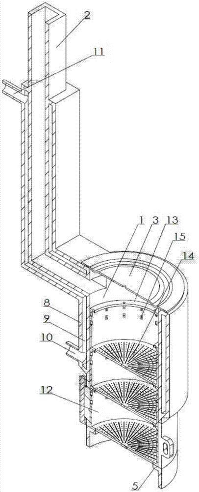
[0011] Examples of the present invention figure 1 , 2 As shown, the multi-layer biofuel heating furnace is provided with a furnace cavity 1 and a smoke exhaust pipe 2; the furnace cavity is a cylindrical combustion chamber, and the upper opening is provided with a circular furnace cover 3, and the furnace cover is provided with an annular depression, which coincides with On the edge of the upper opening, the furnace cavity wall is connected with a smoke exhaust pipe connected to the interior near the upper opening. The inner wall of the furnace cavity is provided with an annular baffle 5 near the lower opening, and 180 openings 6 are arranged on the side wall of the upper furnace cavity of the annular baffle. There is an opening door 7, which is hinged on one side of the opening and can be opened and closed. An outer wall 8 is connected to the outer side of the furnace chamber side wall and the smoke exhaust pipe wall at the upper part of the opening to form a water holding ch...


PUM


Abstract

The invention discloses a multilayer biofuel heating furnace. The multilayer biofuel heating furnace is characterized by comprising a furnace cavity and a smoke discharge pipe; the furnace cavity is cylindrical; a furnace cover is arranged in an upper opening; the wall, near the upper opening, of the furnace cavity is connected with the smoke discharge pipe communicated with the internal; the inner wall, near a lower opening, of the furnace cavity is provided with an annular baffle plate; an opening 180 is formed in the side wall of the furnace cavity in the upper part of the annular baffle plate; a door is arranged in the opening; outer walls are connected to the side wall of the furnace cavity of the upper part of the opening and the outer side of the wall of the smoke discharge pipe, and form a water accommodating cavity; the lower part of the water accommodating cavity is connected with a water inlet pipe; the upper part of the water accommodating cavity is connected with a water outlet pipe; 3-5 fuel boxes are stacked on the annular baffle plate; the fuel boxes have circular side walls bonded on the inner wall of the furnace cavity; inner flanges are arranged at the upper ends of the circular side walls; bottoms with holes are connected to the lower parts of the circular side walls; side holes are formed in the circular side walls; and the heights of the fuel boxes are 4 / 5 to 2 / 3 of the height of the opening. The multilayer biofuel heating furnace cannot accumulate dust for long-time use, reduces non-burnt particles to be mixed in the dust for leakage, and is high in combustion efficiency.

Description

technical field [0001] The invention relates to a heating appliance utilizing biofuel particles, in particular to a multi-layer biofuel heating stove. Background technique [0002] With the vigorous development of the economy and the progress of social production, the excessive consumption of energy has caused huge damage to the environment on which human beings depend, and it is imminent to find new clean and renewable alternative energy sources. Our country is a large agricultural country, and a large amount of straw is burned in the farmland every year, which not only aggravates the environmental pollution, such as the frequent occurrence of smog weather, but also wastes energy, the heat energy of the straw cannot be used, and the straw cannot be fully and effectively used. Utilization mainly lies in the electrification of rural life. People no longer rely on straw for cooking, so there is too much surplus. Straw is directly used in industrial production, and its energy p...

Claims


Application Information

Patent Timeline
IPC IPC(8): F24B1/183F24B1/193
CPCF24B1/183F24B1/193
Inventor 赵正美
Owner CHONGQING HUAWANLUN BIOLOGICAL NEW ENERGY TECH CO LTD
Why Eureka
Try Eureka