
Electromagnetic proportional flow valve

A proportional flow valve, electromagnetic technology, applied in the direction of sliding valve, valve details, valve device, etc., can solve the problems that cannot meet the requirements of high-precision occasions, the control accuracy of the proportional valve port is not high, and the price is high

Active Publication Date: 2016-03-30
浙江三尚智迪科技有限公司
View PDF8 Cites 12 Cited by
  • Summary
  • Abstract
  • Description
  • Claims
  • Application Information

AI Technical Summary

Problems solved by technology

At present, the speed of the actuator is usually controlled by manually adjusting the throttle valve in the hydraulic system. In the hydraulic system that requires stepless speed regulation, the imported proportional flow valve is used. The imported proportional flow valve is expensive and the flow fluctuates greatly. , the control accuracy of the opening amount of the valve port of the proportional valve is not high, which cannot meet the requirements of high-precision occasions

Method used


Image

  • Electromagnetic proportional flow valve
  • Electromagnetic proportional flow valve
  • Electromagnetic proportional flow valve

Examples


Embodiment Construction

[0023] The technical solutions of the embodiments of the present invention will be explained and described below in conjunction with the accompanying drawings of the embodiments of the present invention, but the following embodiments are only preferred embodiments of the present invention, not all of them. Based on the examples in the implementation manners, other examples obtained by those skilled in the art without making creative efforts all belong to the protection scope of the present invention.

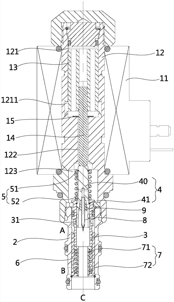
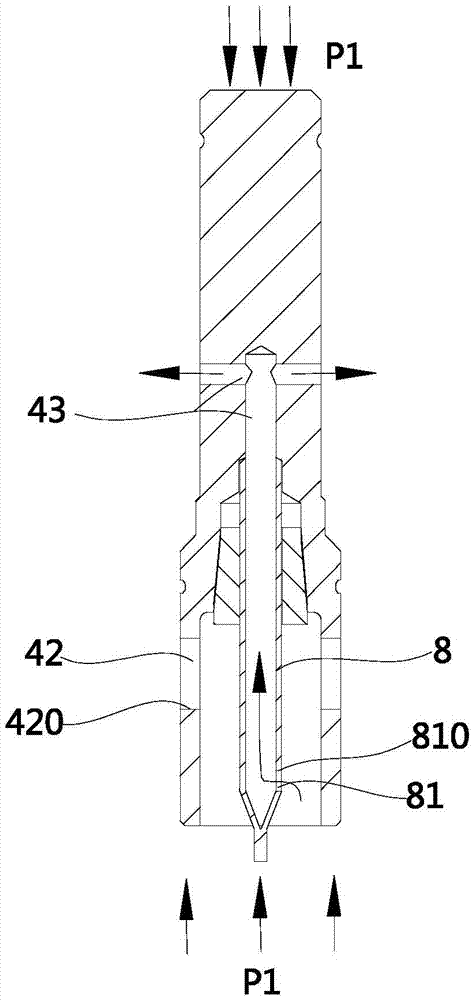
[0024] Such as figure 1 As shown, it is a schematic structural diagram of an electromagnetic proportional flow valve in a preferred embodiment of the present invention, including an electromagnetic drive mechanism, a valve sleeve 2, a valve seat 3, a throttle spool 4 and a spool 6, wherein the electromagnetic drive mechanism includes a coil 11 , magnetic sleeve 12, moving iron 13 and push rod 14, the coil 11 is installed on the outside of the magnetic sleeve 12, the magnetic sle...


PUM


Abstract

The invention discloses an electromagnetic proportional flow valve, and belongs to the technical field of hydraulic control valves. The electromagnetic proportional flow valve solves the technical problem that an existing electromagnetic proportional flow valve is poor in stability and low in control accuracy. The electromagnetic proportional flow valve comprises an electromagnetic driving mechanism, a valve sleeve, a valve base and a throttle valve element; the valve sleeve is fixedly connected between the electromagnetic driving mechanism and the valve base, and the electromagnetic driving mechanism is used for pushing the throttle valve element to downwards move in the valve base in the axial direction; a pressure release channel is arranged in the throttle valve element, and a variable throttle opening is formed in the lateral wall of the throttle valve element; and a pressure guide pipe is further arranged in the throttle valve element, the upper end of the pressure guide pipe is communicated with the pressure release channel, and a pressure guide opening is further formed in the pressure guide pipe and located below the variable throttle opening. The electromagnetic proportional flow valve is mainly applied to high-speed and low-speed switching control systems for execution mechanisms such as oil cylinders and motors.

Description

【Technical field】 [0001] The invention relates to an electromagnetic proportional flow valve, which belongs to the technical field of hydraulic control valves. 【Background technique】 [0002] Under the action of the proportional electromagnet, the proportional flow valve can realize the proportional control of the pressure, flow and other parameters of the hydraulic system. The so-called proportional control is to control the proportional valve spool by changing the current value of the internal coil of the proportional electromagnet through the controller. The moving distance can change the opening of the proportional valve port to realize proportional control. At present, the speed of the actuator is usually controlled by manually adjusting the throttle valve in the hydraulic system. In the hydraulic system that requires stepless speed regulation, the imported proportional flow valve is used. The imported proportional flow valve is expensive and the flow fluctuates greatly...

Claims


Application Information

Patent Timeline
Patent Type & Authority Applications(China)
IPC IPC(8): F16K31/06F16K3/26F16K3/314
CPCF16K3/265F16K3/314F16K31/0668
Inventor 王波罗占涛姚海峰
Owner 浙江三尚智迪科技有限公司
Learn More