compressor

A compressor and compression chamber technology, applied in the field of compressors, can solve the problems of low compression efficiency and reduced gas suction, and achieve the effects of improving compression efficiency, ensuring suction and low manufacturing cost

Active Publication Date: 2019-07-30
ZHUHAI GREE REFRIGERATION TECH CENT OF ENERGY SAVING & ENVIRONMENTAL PROTECTION
View PDF6 Cites 0 Cited by
  • Summary
  • Abstract
  • Description
  • Claims
  • Application Information

AI Technical Summary

Problems solved by technology

[0004] The purpose of the present invention is to provide a compressor to solve the problems of reduced gas suction and low compression efficiency due to the increase in temperature of compressor parts in the prior art

Method used


Image

  • compressor
  • compressor
  • compressor

Examples


Embodiment Construction

[0021] The embodiments of the present invention will be described in detail below with reference to the accompanying drawings, but the present invention can be implemented in many different ways defined and covered by the claims.

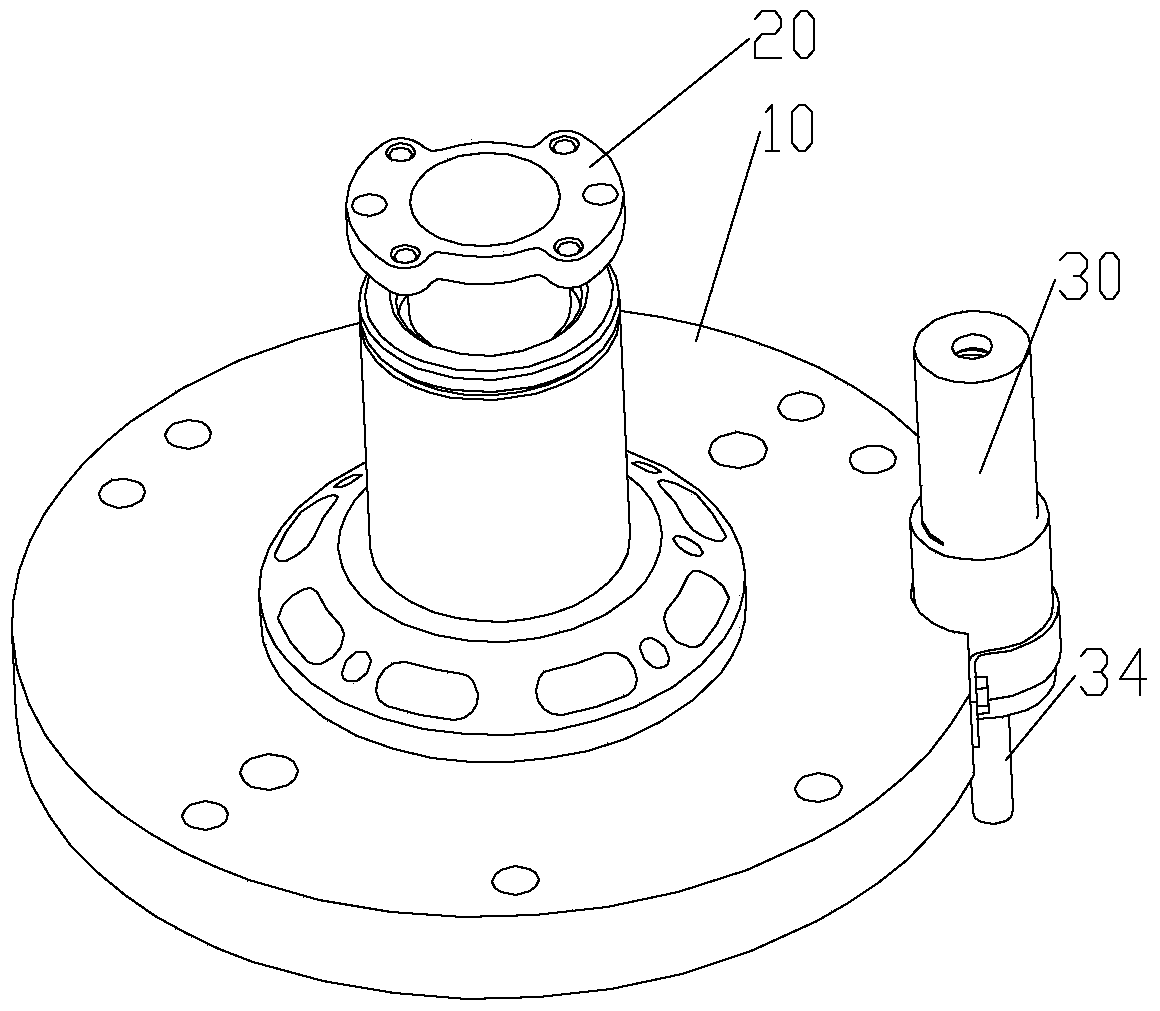
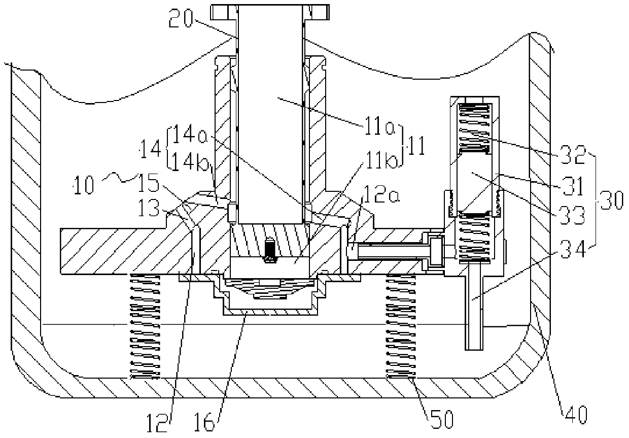
[0022] The invention provides a compressor. Such as Figure 1 to Figure 3 As shown, the compressor includes a cylinder 10, a piston 20 and an oil supply portion 30. The cylinder 10 has a piston passage 11 and a cooling chamber 12 arranged around the circumference of the piston passage 11. The cooling chamber 12 is located at one end of the compression chamber of the piston passage 11. , at least a part of the cooling chamber 12 communicates with the outer surface of the cylinder 10; the piston 20 is slidably disposed in the piston passage 11, and the piston 20 separates the piston passage 11 into a rod chamber 11a and a rodless chamber 11b, and the rodless chamber 11b is a compression chamber ; The outlet end of the oil supply part 30 communicates ...


PUM


Abstract

The invention provides a compressor. The compressor comprises an air cylinder, a piston and an oil supply part. The air cylinder is provided with a piston channel and a cooling cavity which is circumferentially arranged around the piston channel; the cooling cavity is located at one end, where a compression cavity is located, of the piston channel; at least part of the cooling cavity is communicated with the outer surface of the air cylinder; the piston is slidably arranged in the piston channel and divides the piston channel into a rod cavity and a rodless cavity which serves as the compression cavity; the outlet end of the oil supply part is communicated with an oil inlet of the cooling cavity. As the cooling cavity of the air cylinder is located at the end, where the compression cavity is located, of the piston channel, oil supplied by the oil supply part enters the cooling cavity and then can absorb a large amount of heat, and the oil carrying a large amount of heat is discharged out of the cooling cavity. Therefore, the direct cooling of the air cylinder and indirect cooling of the piston are achieved, sucked air is prevented from being heated, the air suction amount is guaranteed, and the compression efficiency of the compressor is improved.

Description

technical field [0001] The present invention relates to the technical field of refrigeration, and more specifically, to a compressor. Background technique [0002] Taking the linear compressor as an example, the motor drives the piston to reciprocate in the cylinder to realize the process of gas suction, compression and discharge. [0003] When the piston repeatedly compresses the gas, a lot of heat will be generated. The heat transfer to the piston and the cylinder will cause the temperature of the piston and the cylinder to rise, so that the gas will be heated when it is sucked into the cylinder, thereby reducing the suction volume of the gas and the compressor. Compression efficiency. Contents of the invention [0004] The present invention aims to provide a compressor to solve the problems in the prior art of reduced gas intake and low compression efficiency due to temperature rise of compressor parts. [0005] In order to solve the above-mentioned technical problems...

Claims


Application Information

Patent Timeline
Patent Type & Authority Patents(China)
IPC IPC(8): F04B39/06
Inventor 黄辉胡余生魏会军崔中黄建平黄传顺陈柱锦梁苡铭张建伟
Owner ZHUHAI GREE REFRIGERATION TECH CENT OF ENERGY SAVING & ENVIRONMENTAL PROTECTION
Why Eureka
Try Eureka