
Two-way continuous shear deformation device and method

A shear deformation and annular technology, applied in the field of plastic forming, can solve the problems of restricted application and uneven thickness of the pipe wall, and achieve the effects of refining the matrix grains, improving the shear uniformity, and reducing the size dispersion.

Active Publication Date: 2017-07-11
SHANGHAI JIAOTONG UNIV
View PDF1 Cites 0 Cited by
  • Summary
  • Abstract
  • Description
  • Claims
  • Application Information

AI Technical Summary

Problems solved by technology

However, almost all grains shear to a certain extent along the pipe axis, showing an elliptical shape; at the same time, when the shear strain at the outer diameter of the aluminum alloy pipe reaches 14, the shear strain at the inner diameter of the pipe is only 2, That is, the shear strain generated by torsion is extremely uneven along the thickness of the pipe wall
In addition, although the torsional strain can theoretically increase infinitely, the friction between the tube blank and the mold limits the increase of the torsional strain. The above-mentioned series of shortcomings seriously restrict the application of this method in the preparation of ultrafine crystal tubular materials with uniform structure.

Method used


Image

  • Two-way continuous shear deformation device and method
  • Two-way continuous shear deformation device and method

Examples


Embodiment Construction

[0055] The present invention will be described in detail below in conjunction with specific embodiments. The following examples will help those skilled in the art to further understand the present invention, but do not limit the present invention in any form. It should be noted that those skilled in the art can make several modifications and improvements without departing from the concept of the present invention. These all belong to the protection scope of the present invention.

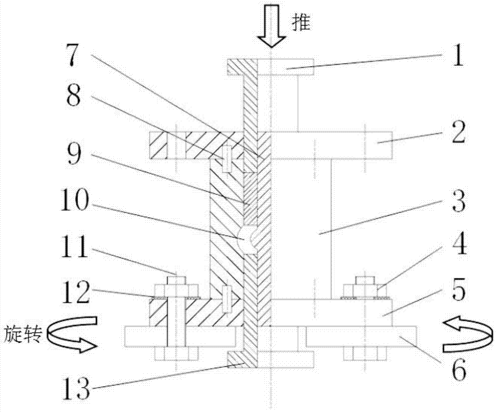
[0056] In this embodiment, the two-way continuous shear deformation device provided by the present invention includes an axially hollow variable-section annular extrusion cylinder 3, a variable-section core rod 7, an upper fixed platen 2, a lower fixed platen 5, an upper annular Extrusion punch 1, lower annular extrusion punch 13 and twisted workbench 6;

[0057] Wherein, the upper end of the variable cross-section annular extrusion cylinder 3 is connected to the upper fixed platen 2, and the lowe...


PUM


Abstract

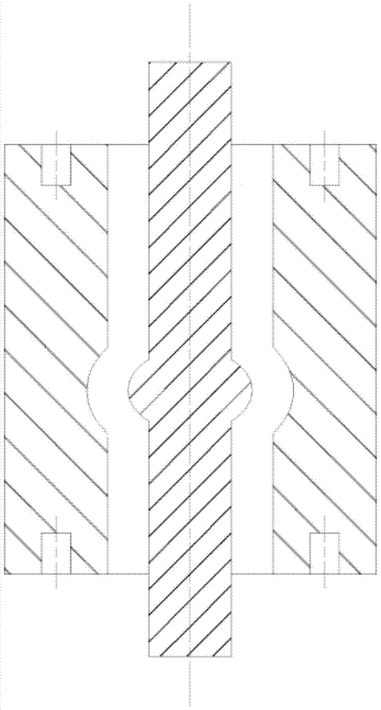
The invention provides a bi-directional continuous shear deformation device which comprises an axial hollow variable cross-section annular extrusion barrel, a variable cross-section core rod, an upper fixing pressure plate, a lower fixing pressure plate, an upper annular extrusion punch, a lower annular extrusion punch and a rotating working table, wherein the upper end of the variable cross-section annular extrusion barrel is connected with the upper fixing pressure plate, and the lower end of the variable cross-section annular extrusion barrel is connected with the lower fixing pressure plate; a groove is formed in the inner wall surface of the variable cross-section annular extrusion barrel; the variable cross-section core rod is arranged on the inner side of the variable cross-section annular extrusion barrel, and is provided with a bulge matched with the groove; the upper annular extrusion punch penetrates through a first through hole of the upper fixing pressure plate to be connected with the upper end of the variable cross-section core rod; the lower annular extrusion punch penetrates through a second through hole of the lower fixing pressure plate to be connected with the lower end of the variable cross-section core rod; and the lower fixing pressure plate is arranged on the rotating working table. According to the bi-directional continuous shear deformation device, a necking down zone in traditional reciprocating extrusion is transformed into a smoothly transitional continuous shear channel, so that the shear uniformity of tubular blanks in the cross section direction is improved.

Description

technical field [0001] The invention relates to plastic forming technology, in particular to a bidirectional continuous shear deformation device and method. Background technique [0002] Ultrafine-grained materials are high-performance materials that combine excellent strength and good plasticity and toughness. The large plastic deformation technology (SPD) has a remarkable grain refinement ability, and is recognized as the most promising method for preparing ultrafine grain (grain size 100nm-1um) and bulk nanometer (grain size less than 100nm) materials. method. [0003] After searching the literature of the prior art, it was found that the Chinese invention patent with the publication number CN103894436A, the name of the invention: a reciprocating extrusion device and processing method for reinforcing magnesium alloy tubes, this technology compresses magnesium alloy tubes through annular reciprocating extrusion Multi-pass processing is carried out to realize the continuo...

Claims


Application Information

Patent Timeline
Patent Type & Authority Patents(China)
IPC IPC(8): B21C23/21
CPCB21C23/212B21C23/217
Inventor 王渠东张利
Owner SHANGHAI JIAOTONG UNIV
Learn More