Resonant-type fiber-optic gyroscope with adjustable sensitivity

A fiber optic gyroscope and sensitivity technology, which is applied in Sagnac effect gyroscopes and other directions, can solve the problems of fixed sensitivity, small dynamic range, and difficulty in measuring rotation speed in a large range

Inactive Publication Date: 2016-03-23
NORTHEAST FORESTRY UNIVERSITY
View PDF6 Cites 3 Cited by
  • Summary
  • Abstract
  • Description
  • Claims
  • Application Information

AI Technical Summary

Problems solved by technology

[0003] Based on the above deficiencies, the present invention provides a sensitivity-adjustable resonant fiber optic gyroscope, which solves the problem that the traditional resonant fiber optic gyroscope has a fixed sensitivity and a relatively small dynamic range, and it is difficult to measure the rotation speed in a large range.

Method used


Image

  • Resonant-type fiber-optic gyroscope with adjustable sensitivity
  • Resonant-type fiber-optic gyroscope with adjustable sensitivity

Examples


Embodiment 1

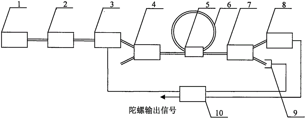
[0017] Such as Figure 1-2 As shown, a resonant fiber optic gyro with adjustable sensitivity includes a first laser 1, a polarization controller 2, a lithium niobate phase modulator 3, a first wavelength division multiplexer 4, a fiber coupler 5, an erbium-doped optical fiber Ring 6, second wavelength division multiplexer 7, second laser 8, detector 9 and signal processing and feedback system 10; the optical output end of the first laser 1 is connected to the optical input end of the polarization controller 2, and the polarization controller The optical output end of 2 is connected with the optical input end of the lithium niobate phase modulator 3, and the optical output end of the lithium niobate phase modulator 3 is connected with the optical input end of the first wavelength division multiplexer 4, and the first wavelength division multiplexer The optical input and output end of the device 4 is connected with the first optical input and output end of the fiber coupler 5, t...

Embodiment 2

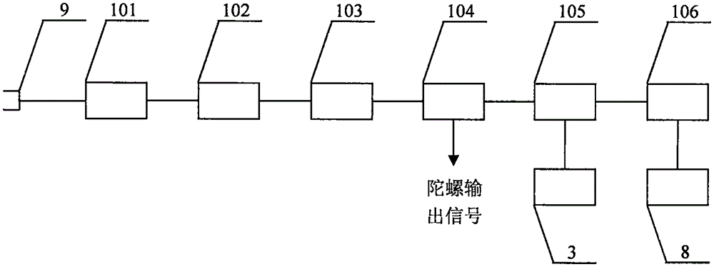
[0021] The working principle of the present invention is: the 1550nm laser with constant output power of the first laser device 1, the 1550nm laser enters the polarization controller 2, enters the lithium niobate phase modulator 3 after selecting the polarization state in the polarization controller 2, and enters the lithium niobate phase modulator 3 in the lithium niobate phase The optical frequency is modulated in the modulator 3, and the 1550nm laser light output by the lithium niobate phase modulator 3 enters the first wavelength division multiplexer 4, then enters the erbium-doped fiber ring 6 through the fiber coupler 5, and passes through the fiber coupler 5 and Resonance occurs in the erbium-doped fiber ring 6. After the 1550nm laser resonates, it enters the detector 9 through the second wavelength division multiplexer 7 and is detected by the detector 9. The output signal of the detector 9 enters the signal processing and feedback system 10 for signal processing. Proce...


PUM


Abstract

The invention discloses a resonant-type fiber-optic gyroscope with adjustable sensitivity. The resonant-type fiber-optic gyroscope comprises two laser devices, a polarization controller, a lithium niobate phase modulator, two wavelength division multiplexers, an optical fiber coupler, an erbium-doped optical fiber ring, a detector and a signal processing and feedback system. The first laser device is connected with the polarization controller, the polarization controller is connected with the lithium niobate phase modulator, the lithium niobate phase modulator is connected with the first wavelength division multiplexer, the first wavelength division multiplexer is connected with the optical fiber coupler, the optical fiber coupler is connected with the erbium-doped optical fiber ring and connected with the second wavelength division multiplexer, the second wavelength division multiplexer is connected with the second laser device and connected with the detector, the detector is connected with the signal processing and feedback system, the signal processing and feedback system is connected with the lithium niobate phase modulator and connected with the second laser device, and the signal processing and feedback system outputs a gyroscope output signal. Compared with a traditional resonant-type fiber-optic gyroscope, the dynamic range of the resonant-type fiber-optic gyroscope is expanded by tens of times.

Description

technical field [0001] The invention relates to the field of fiber optic gyroscopes, in particular to a resonant fiber optic gyroscope with adjustable sensitivity. Background technique [0002] In 1976, V.Vali and R.W.Shorthill of Utah University in the United States successfully developed the first fiber optic gyroscope. As soon as the fiber optic gyroscope came out, it attracted many national universities and colleges with its advantages of simple structure, small size, long life, and low power consumption. The attention of scientific research institutions has been developed rapidly. At present, the traditional resonant fiber optic gyroscope uses a fiber optic ring resonator made of a single-mode fiber. When the gyro rotates, the resonant frequency of the fiber optic ring resonator will change with the rotational angular velocity, so by detecting the fiber optic ring resonant frequency The change of the rotational angular velocity can be measured, but the sensitivity of t...

Claims


Application Information

Patent Timeline
Patent Type & Authority Applications(China)
IPC IPC(8): G01C19/72
CPCG01C19/72
Inventor 田赫苏润洲
Owner NORTHEAST FORESTRY UNIVERSITY
Why Eureka
Try Eureka