
Method for detecting robot precision by projection imaging of material allowing quick conversion between solid phase and liquid phase

A technology of rapid conversion and imaging detection, applied in instruments, measuring devices, optical devices, etc., can solve the problems of many models, complex access structure, high cost, and achieve enhanced test accuracy, high degree of intelligence, and reduced investment. Effect

Active Publication Date: 2016-03-23
重庆凯瑞机器人技术有限公司 +1
View PDF6 Cites 2 Cited by
  • Summary
  • Abstract
  • Description
  • Claims
  • Application Information

AI Technical Summary

Problems solved by technology

[0002] Robots are widely used in industrial processing fields due to their high processing precision, wide range and simple processing methods. Robots need to be calibrated before use or after long-term use. Traditional calibration methods include, for example, the test probe method. A sufficient number of displacement or proximity sensor probes to measure real-world pose characteristics; laser beam trajectory comparison method, measuring trajectory accuracy / repeatability along the laser beam with a photoelectric sensor that detects positional errors of incident light to the sensor center ; The existing detection technology is to realize the detection during the motion of the industrial robot. The detection must be completed in conjunction with the motion programming operation of the industrial robot. It has many models, complex types, high technical difficulty, poor versatility, complex access structure, and high cost. The efficiency is low, the data after detection has no production value, and the detection data has no time-domain analysis value

Method used


Image

  • Method for detecting robot precision by projection imaging of material allowing quick conversion between solid phase and liquid phase
  • Method for detecting robot precision by projection imaging of material allowing quick conversion between solid phase and liquid phase
  • Method for detecting robot precision by projection imaging of material allowing quick conversion between solid phase and liquid phase

Examples


Embodiment Construction

[0029] The preferred embodiments of the present invention will be described in detail below in conjunction with the accompanying drawings, so that the advantages and features of the present invention can be more easily understood by those skilled in the art, so as to define the protection scope of the present invention more clearly.

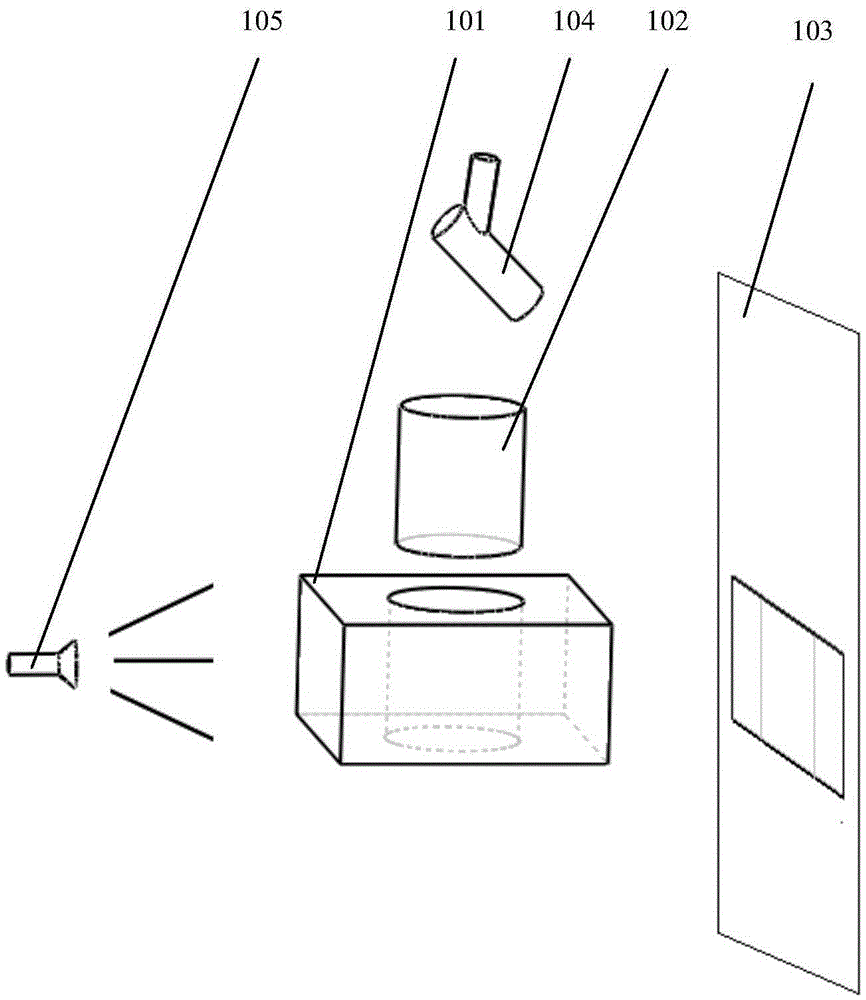
[0030] Such as Figure 1 to Figure 7 Shown: a method for detecting the accuracy of a robot using projection imaging of solid-liquid phase rapid conversion materials, the specific steps are as follows,

[0031] Step 1: Prefabricate a test mold cavity made of transparent glass, and the test mold cavity can be concave conical, circular, square, hexagonal, hemispherical, or in various shapes as required The combination;

[0032] Step 2: Use the tested robot to process ice cubes from -18 degrees Celsius to -4 into cones, cylinders, cuboids, tetrahedrons, cuboids, or hemispherical test pieces. Use dry ice mist to maintain the temperature of the ice c...


PUM

PropertyMeasurementUnit
Melting pointaaaaaaaaaa

Abstract

A method for detecting robot precision by projection imaging of a material allowing quick conversion between a solid phase and a liquid phase specifically comprises the steps that at the step 1, a transparent testing mold cavity is prefabricated; at the step 2, a tested robot uses the solid material allowing the quick conversion between the solid phase and the liquid phase to process a testing part, and the testing part is corresponding to the testing mold cavity in shape; at the step 3, the testing part is put into the testing mold cavity; at the step 4, a light source is aligned to the testing mold cavity from a side direction; at the step 5, a projected image of the testing part in the testing mold cavity is collected; and at the step 6, the projected image is analyzed to obtain a processing precision value of the robot. The method for detecting the robot precision by the projection imaging of the material allowing the quick conversion between the solid phase and the liquid phase provided by the invention can be operated easily, wherein the testing part has a simple geometric figure, so that the testing part can be processed quickly through simple programming of the robot; and the material allowing the quick conversion between the solid phase and the liquid phase is applied, can be converted into a liquid at a temperature between 0 DEG C and 100 DEG C, can be solubilized for reutilization after testing, generates no substance discharge, and is energy-saving and environment-friendly.

Description

technical field [0001] The invention relates to the field of precision detection, optimization and analysis of robot processing performance, in particular to a method for detecting the precision of a robot by using projection imaging of solid-liquid phase rapid conversion materials. Background technique [0002] Robots are widely used in industrial processing fields due to their high processing precision, wide range and simple processing methods. Robots need to be calibrated before use or after long-term use. Traditional calibration methods include, for example, the test probe method. A sufficient number of displacement or proximity sensor probes to measure real-world pose characteristics; laser beam trajectory comparison method, measuring trajectory accuracy / repeatability along the laser beam with a photoelectric sensor that detects positional errors of incident light to the sensor center ; The existing detection technology is to realize the detection during the motion of t...

Claims


Application Information

Patent Timeline
IPC IPC(8): G01B11/00
CPCG01B11/00
Inventor 何荣虎邹芳李金学黄武凯
Owner 重庆凯瑞机器人技术有限公司
Learn More