An air-controlled gas pressure reducer

A pressure reducer and air control technology, applied in the direction of the valve's fluid energy absorption device, valve housing structure, valve operation/release device, etc., to achieve high reliability of mechanical properties, smooth gas flow, and easy inspection

Active Publication Date: 2020-10-16
NAT UNIV OF DEFENSE TECH
View PDF7 Cites 0 Cited by
  • Summary
  • Abstract
  • Description
  • Claims
  • Application Information

AI Technical Summary

Problems solved by technology

[0008] The purpose of the present invention is to solve the technical problem that the existing pressure reducer cannot realize the direct decompression of the high-pressure gas above 20MPa with a flow rate greater than 10kg / s to a state below 10MPa and stabilize the pressure

Method used


Image

  • An air-controlled gas pressure reducer
  • An air-controlled gas pressure reducer
  • An air-controlled gas pressure reducer

Examples


Embodiment Construction

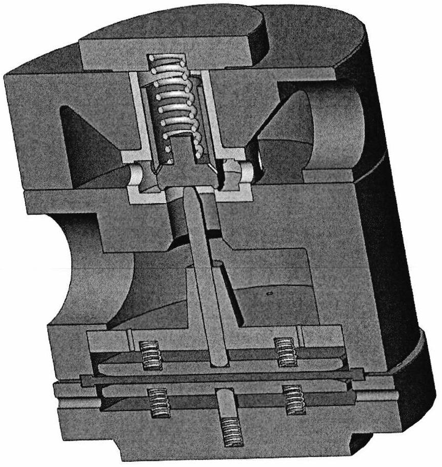
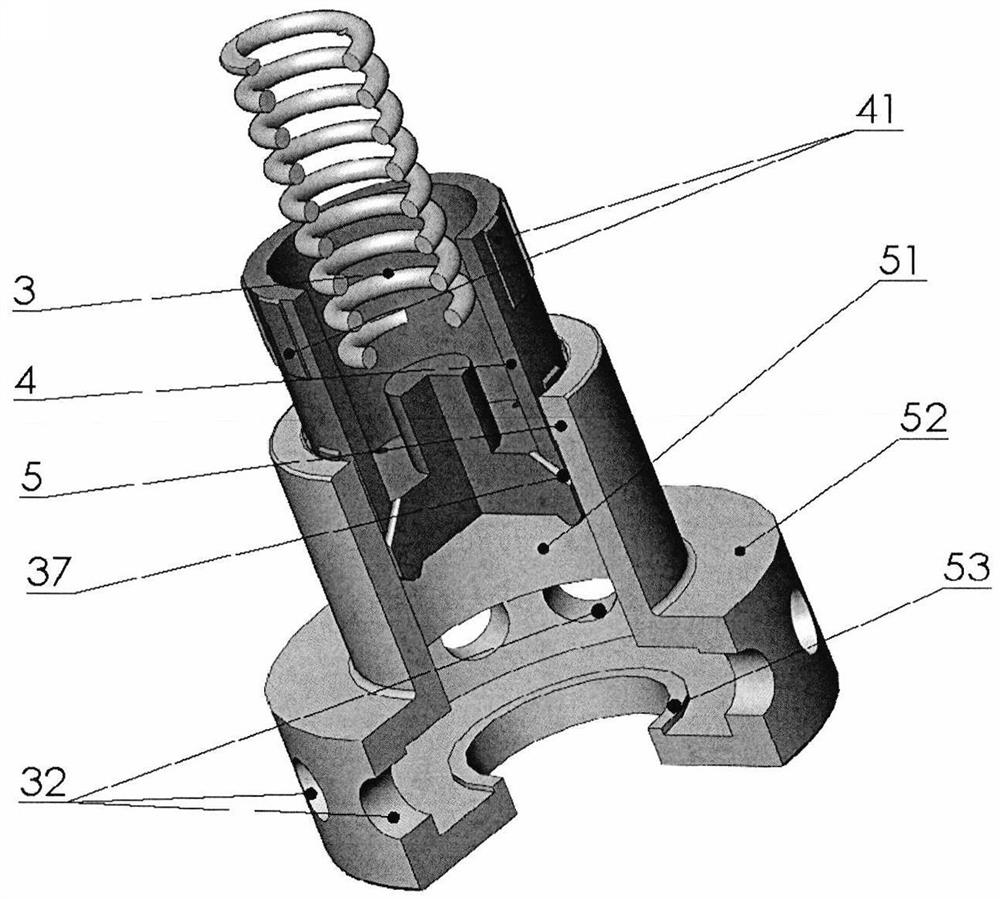
[0040] The specific structure of the pressure reducer of the present invention will be described below in conjunction with the accompanying drawings.

[0041] Such as Figure 1A , 1B As shown, the gas pressure reducer of the present invention has the structural characteristics of "two pieces, three bodies and four cavities", and specifically includes an input cavity 21, an output cavity 22, a damping cavity 23 and a control cavity 24; the upper valve body 2, the middle valve body 7 and the Lower valve body 14; sensing assembly and throttling assembly.

[0042]The input chamber 21 is an annular cavity surrounded by the upper valve body 2, the middle valve body 7 located on the bottom surface of the chamber and the throttling assembly located in the center of the chamber. The upper valve body 2 is a cylinder with a hole in the middle as a whole, made of metal materials such as high-strength stainless steel, and an annular chamber with an "M" cross-section is processed inside, w...


PUM


Abstract

The invention provides a pneumatic-control type pressure reducer and belongs to the technical field of conveying and supplying of high-pressure and intermediate-pressure media. The pneumatic-control type pressure reducer comprises an input cavity, an output cavity, a damping cavity, a control cavity, a throttling assembly, a sensing assembly, an upper valve body, a middle valve body, a lower valve body and an isolation tray. The input cavity is an annular containing cavity defined by the upper valve body, the middle valve body located on the bottom face of the cavity, and the throttling assembly located in the center of the cavity. The output cavity is an annular containing cavity defined by the middle valve body, the isolation tray located on the bottom face of the cavity, and the throttling assembly located on the upper base of the cavity. The damping cavity and the control cavity are defined by the middle valve body, the lower valve body and the isolation tray. The control cavity is used for inflating control gas. The damping cavity is used for inflating output gas with the pressure being reduced. The throttling assembly is used for reducing and stabilizing the pressure of high-pressure gas and isolating the input cavity from the output cavity. The sensing assembly is used for sensing pressure regulating signals and working parameters of the pressure reducer, then transmitting the pressure regulating signals and the working parameters to the throttling assembly and isolating the damping cavity from the control cavity. By means of the pressure reducer, pressure reduction and stabilization of large-flow gas can be achieved rapidly and stably.

Description

technical field [0001] The invention belongs to the technical field of aerospace, and specifically relates to the technical field of high-pressure and medium-pressure medium transportation and supply. Background technique [0002] The pressure reducer is a kind of regulating valve, which reduces the inlet pressure to the required outlet pressure value through the throttling effect of the valve core, and controls the opening of the valve core through the feedback of the outlet pressure to maintain the stability of the outlet pressure. It can be seen that the function of the pressure reducer is to decompress the upstream gas pressure and stabilize it at the desired value. In fact, the pressure reducer uses the throttling effect of the airflow to achieve pressure regulation. Generally, when the high-pressure gas passes through the narrow cross-section between the valve core and the valve seat, a throttling phenomenon occurs, and a part of the pressure energy is converted into ...

Claims


Application Information

Patent Timeline
Patent Type & Authority Patents(China)
IPC IPC(8): F16K1/00F16K1/36F16K27/02F16K31/126F16K47/08
CPCF16K1/00F16K1/36F16K27/02F16K31/1266F16K47/08
Inventor 李清廉郑丽赖林徐万武王振国
Owner NAT UNIV OF DEFENSE TECH
Why Eureka
Try Eureka