
An energy-feeding type vibration isolation device

A technology of energy-feeding and energy-storage devices, which is applied in the field of energy-feeding vibration isolation devices, can solve the problems of increasing vehicle fuel consumption, dissipation, and failure to meet energy conservation and emission reduction, and achieve effective unity of vibration energy recovery and vibration isolation, The effect of high output power and low cost

Active Publication Date: 2017-10-20
JIANGSU UNIV
View PDF1 Cites 0 Cited by
  • Summary
  • Abstract
  • Description
  • Claims
  • Application Information

AI Technical Summary

Problems solved by technology

At present, we usually use the traditional double cylinder hydraulic shock absorber on the passive suspension, such as the hydraulic shock absorber disclosed in patent CN93202010.0, the variable damping shock absorber disclosed in CN201020616405.5, etc. When the liquid repeatedly flows from one cavity to another, the friction between the liquid molecules and the hole wall forms a vibration damping force, but this kind of shock absorber dissipates the vibration energy of the suspension in the form of heat energy, which indirectly increases reduce the fuel consumption of vehicles, which does not meet the theme of energy saving and emission reduction in today's society

Method used


Image

  • An energy-feeding type vibration isolation device
  • An energy-feeding type vibration isolation device
  • An energy-feeding type vibration isolation device

Examples


Embodiment Construction

[0030] In describing the present invention, it is to be understood that the terms "upper", "lower", "front", "rear", "left", "right", "top", "bottom", "inner", "outer" ” and other indicated orientations or positional relationships are based on the orientations or positional relationships shown in the accompanying drawings, which are only for the convenience of describing the present invention and simplifying the description, rather than indicating or implying that the referred device or element must have a specific orientation, with a specific configuration and operation, and therefore should not be construed as limiting the invention.

[0031] In the present invention, unless otherwise clearly specified and limited, terms such as "installation", "connection", "connection" and "fixation" should be understood in a broad sense, for example, it can be a fixed connection or a detachable connection , or integrally connected; it may be mechanically connected or electrically connecte...


PUM


Abstract

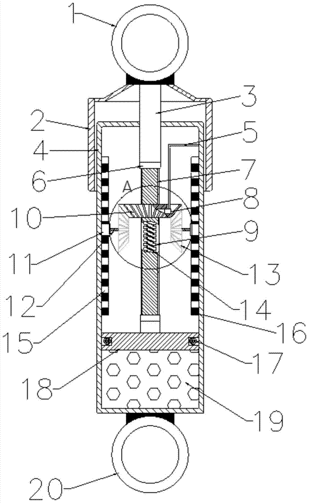
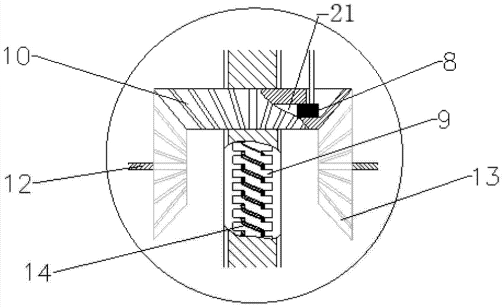
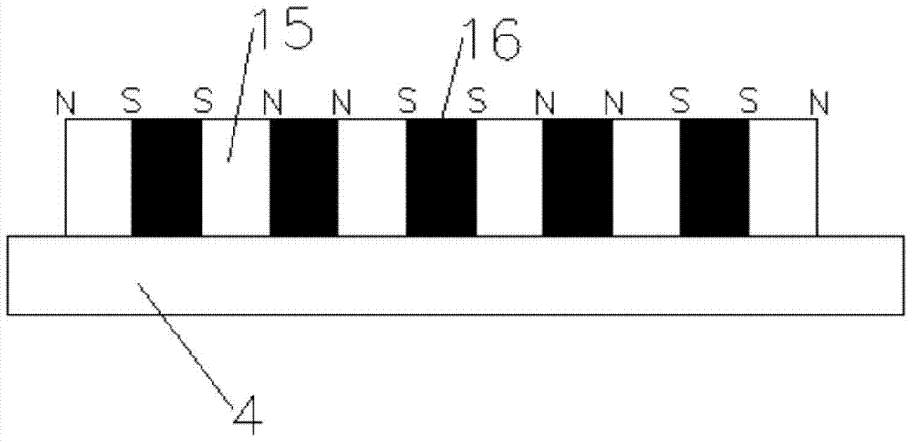
The invention belongs to an energy feeding type vibration isolating device in the field of energy conservation and emission reduction of automobiles. The device comprises a cylinder barrel, a ball screw type piston rod, a main bevel gear, auxiliary bevel gears and an energy storing device. Grooves where an electromagnetic coil is wound are evenly distributed in the ball screw type piston rod in the axial direction. The electromagnetic coil is electrically connected with the input end of the energy storing device. Permanent magnets and iron cores are alternately arranged on the inner wall of the cylinder barrel by a circle in the axial direction. The main bevel gear is meshed with a ball screw structure through internal threads. The two sides of the main bevel gear are meshed with the auxiliary bevel gears respectively through external threads. Vertical movement of a suspension frame is converted into rotating movement through the ball screw structure, and therefore the purpose of isolating automobile vibration through movement state conversion is achieved. When the permanent magnets and the closed electromagnetic coil relatively move, an electromagnetic coil winding will generate induced current so that induced electromotive force can be generated, vibration energy is recycled so that energy conservation of an automobile can be achieved, and the purposes of energy conservation and emission reduction are achieved.

Description

technical field [0001] The invention relates to the field of automobile energy saving and emission reduction, and specifically relates to an energy-feeding type vibration isolation device. Background technique [0002] The vibration isolation device is a kind of shock absorber that installs machinery or instruments on suitable elastic devices to isolate vibration. Shock absorber is a crucial part of the car suspension, and its performance directly affects the ride comfort and handling stability of the car. At present, we usually use the traditional double cylinder hydraulic shock absorber on the passive suspension, such as the hydraulic shock absorber disclosed in patent CN93202010.0, the variable damping shock absorber disclosed in CN201020616405.5, etc. When the liquid repeatedly flows from one cavity to another, the friction between the liquid molecules and the hole wall forms a vibration damping force, but this kind of shock absorber dissipates the vibration energy of t...

Claims


Application Information

Patent Timeline
Patent Type & Authority Patents(China)
IPC IPC(8): F16F9/32F16F9/36
CPCF16F9/3207F16F9/3214F16F9/3221F16F9/36F16F9/368
Inventor 陈龙汪佳佳汪若尘丁仁凯余未
Owner JIANGSU UNIV
Learn More