Automatic-oiling rotating shuttle shaft structure and rotating shuttle box of embroidery machine

A technology of automatic refueling and hook shaft, which is applied to embroidery machines, embroidery machine mechanisms, textiles and papermaking, etc. It can solve the problems of hook shaft jamming, wrong filling time, and high manual maintenance costs, so as to reduce waste and Pollution, good sealing effect

Active Publication Date: 2016-03-23
JIANGXI HEFENG ELECTRONICS MACHINES
View PDF8 Cites 4 Cited by
  • Summary
  • Abstract
  • Description
  • Claims
  • Application Information

AI Technical Summary

Problems solved by technology

[0002] In the prior art, the lubrication of the rotary shaft of the rotary hook box mainly adopts the method of manual regular filling of lubricating oil, and manual filling of lubricating oil

Method used


Image

  • Automatic-oiling rotating shuttle shaft structure and rotating shuttle box of embroidery machine
  • Automatic-oiling rotating shuttle shaft structure and rotating shuttle box of embroidery machine
  • Automatic-oiling rotating shuttle shaft structure and rotating shuttle box of embroidery machine

Examples


Embodiment Construction

[0042] In order to fully understand the technical content of the present invention, the technical solution of the present invention will be further introduced and illustrated below in conjunction with schematic diagrams, but is not limited thereto.

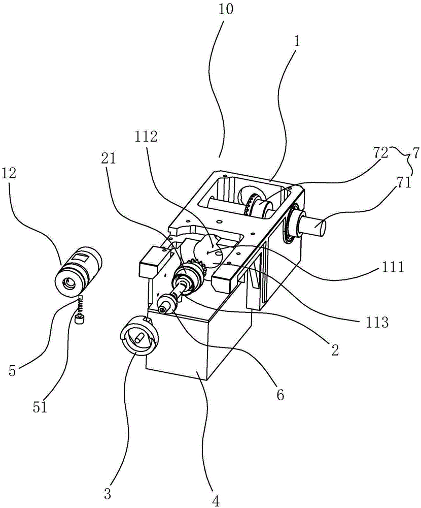
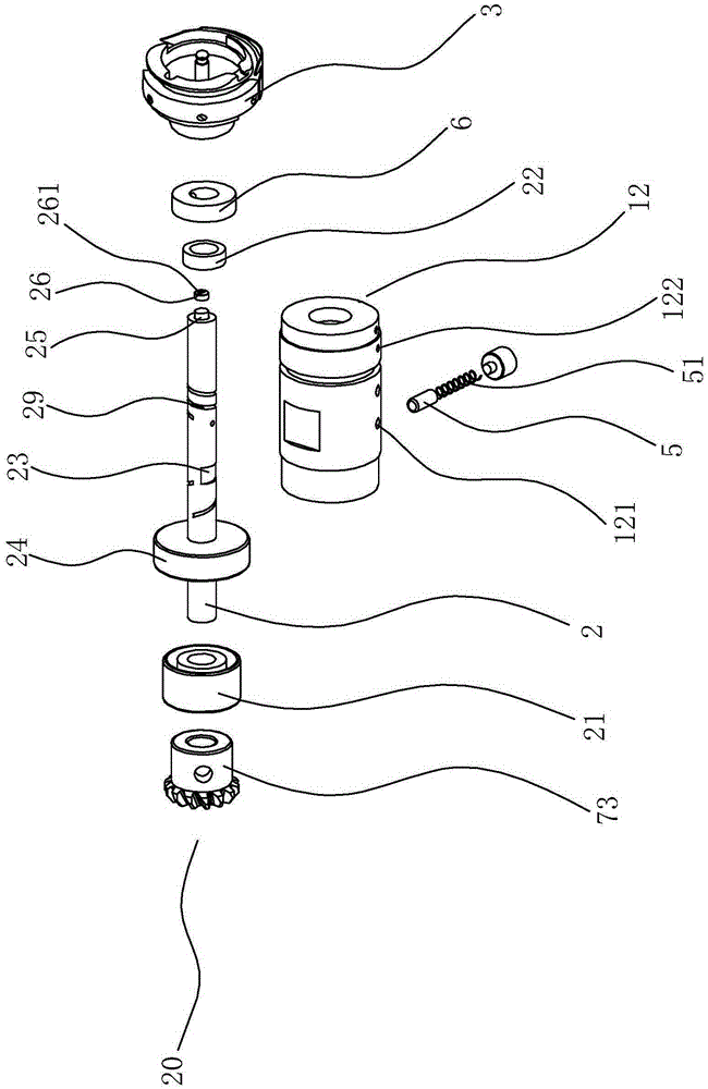
[0043] Such as figure 1 As shown, a rotary hook box 10 of an embroidery machine comprises a rotary hook box 1, a rotating shaft 2 connected to the rotary hook box 1 by transmission, a rotary hook 3 connected to the rotary shaft 2 by transmission, a lubricating oil tank 4, a piston column head 5, and a piston The elastic member 51, the left oil seal 21 and the right oil seal (combined with figure 2 ), for pressing the right oil seal (combined figure 2 ), the positioning retaining ring 6, the power unit 7 fixed on the hook box 1.

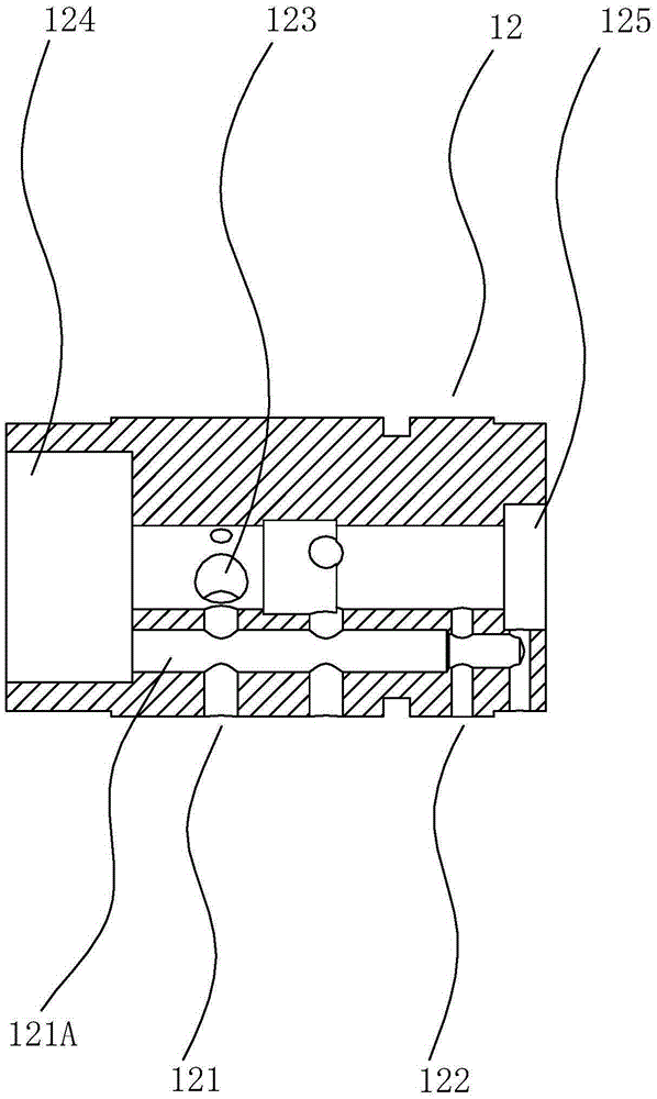
[0044] The hook box 1 includes a box body 11 and a sleeve 12 sleeved on the outer periphery of the rotating shaft 2 . The casing 11 is provided with an oil inlet pipeline 111 and an oil outlet pipeli...


PUM


Abstract

The invention discloses an automatic-oiling rotating shuttle shaft structure and a rotating shuttle box of an embroidery machine. The automatic-oiling rotating shuttle shaft structure comprises the rotating shuttle box, a rotating shaft and a rotating shuttle, wherein the rotating shaft is in transmission connection with the rotating shuttle box; the rotating shuttle is in transmission connection with the rotating shaft; the rotating shuttle box comprises a box body and a shaft sleeve which is arranged at the periphery of the rotating shaft in a sleeving way; an axial hole which is used for fixing the shaft sleeve is formed in the box body; an axial oil storage hole which does not penetrate through the rotating shaft, a plurality of oil grooves which are formed in the outer surface of the rotating shaft and a connecting hole which is communicated with the oil storage hole and the outer surface of the rotating shaft are formed in the rotating shaft; the rotating shaft is also provided with an oil absorption piece which is contained in the oil storage hole and an oil soaking screw which is fixedly arranged at the opening end of the oil storage hole; an oil outlet hole which is communicated with the oil storage hole and the exterior is formed in the oil soaking screw; the rotating shaft is rotationally connected to the box body; an oil inlet passage and an oil outlet passage are formed in the shaft sleeve; one section of each of the oil grooves is connected with the oil inlet passage when the rotating shaft rotates. The automatic-oiling rotating shuttle shaft structure disclosed by the invention has high practicability, can solve practical problems and can be widely promoted and applied to a market.

Description

technical field [0001] The invention relates to a rotating shaft structure and an embroidery machine, in particular to a rotary hook shaft structure and an embroidery machine rotary hook box. Background technique [0002] In the prior art, the lubrication of the rotary shaft of the rotary hook box mainly adopts the method of manual regular filling of lubricating oil, and manual filling of lubricating oil may result in over-filling, under-filling, and wrong filling time, which is easy to cause the hook shaft The phenomenon of stuck, and the cost of manual maintenance is high. Contents of the invention [0003] In order to overcome the disadvantages of the above-mentioned prior art, the object of the present invention is to provide an automatic refueling hook shaft structure and an embroidery machine hook box. [0004] The technical scheme of the present invention is: a rotary hook shaft structure for automatic refueling, including a rotary hook box, a rotating shaft connec...

Claims


Application Information

Patent Timeline
IPC IPC(8): D05C11/18D05C13/04
CPCD05C11/18D05C13/04
Inventor 陈学生张叶辉汤少平
Owner JIANGXI HEFENG ELECTRONICS MACHINES
Why Eureka
Try Eureka