Yarn feeding device, yarn storage wheel of yarn feeding device and assembly method thereof

An assembly method and a yarn storage wheel technology are applied in textiles and papermaking, knitting, weft knitting, etc., which can solve problems such as increased product defect rate, increased production cost, and exposed burrs, so as to reduce production costs, save man-hours, and avoid The effect of snagging

Inactive Publication Date: 2018-09-14
TIEN YANG KNITTING MACHINERY
View PDF6 Cites 0 Cited by
  • Summary
  • Abstract
  • Description
  • Claims
  • Application Information

AI Technical Summary

Problems solved by technology

[0003] However, these slots are arranged on the outer edge of the lower wheel body, openings will be formed on the outer edge of the lower wheel body, and there are at least a dozen yarn storage nails and slots, so it is easy to produce burrs The lower end of the yarn storage nail in the groove is located on the outer edge of the lower wheel body, and the burr at the lower end of the yarn storage nail will also be exposed on the outer edge of the lower wheel body
Furthermore, during the assembly process when the lower ends of these yarn storage nails are inserted into these slots, burrs are also likely to be produced due to the extrusion between the yarn storage nails and the slots, and the burrs will also be exposed to the bottom of the lower wheel body. outer edge
[0004] Therefore, the yarn passing through the yarn storage wheel is prone to the problem of snagging due to burrs, which will cause defects in the cloth and increase the defective rate of the product. The defective rate can even be as high as 30%, and the types of yarns used will also be limited.
Therefore, the existing yarn storage wheel must undergo quality inspection, which is labor-intensive and time-consuming, resulting in an increase in production costs, and the method of visual quality inspection is still prone to misjudgment by quality inspectors, which will increase the defect rate of the product , will cause subsequent maintenance and return troubles, and some customers may even request the return of the entire knitting machine, resulting in a huge loss of the industry's economy and goodwill
[0005] In addition, these slots are arranged on the outer edge of the lower wheel body. During the high-speed rotation of the yarn storage wheel, the yarn storage nails will fly out due to the centrifugal force, which will cause damage to the yarn storage wheel and even the yarn feeding device. , there will also be the above-mentioned troubles of maintenance and return

Method used


Image

  • Yarn feeding device, yarn storage wheel of yarn feeding device and assembly method thereof
  • Yarn feeding device, yarn storage wheel of yarn feeding device and assembly method thereof
  • Yarn feeding device, yarn storage wheel of yarn feeding device and assembly method thereof

Examples


no. 1 example

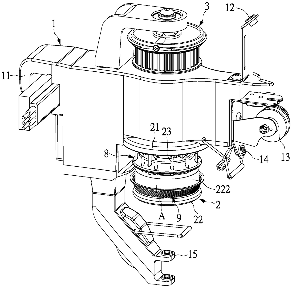
[0067] see figure 1 , the present invention provides a yarn feeding device, the yarn feeding device includes a body 1 and a yarn storage wheel 2, the yarn storage wheel 2 is rotatably connected to the body 1, the yarn storage wheel 2 can be connected to a Pulley 3, the pulley 3 can be used to engage with belt elements such as belts (not shown) to drive the pulley 3 and the yarn storage wheel 2 to rotate, so that the yarn storage wheel 2 drives the yarn to store and send yarn.

[0068] In this embodiment, an electromagnetic clutch type yarn feeding device is disclosed, but it is not limited thereto. The present invention can also be applied to motor type or other types of yarn feeding devices. In another embodiment, it is a motor type The yarn feeding device can utilize a motor (figure omitted) to directly drive the yarn storage wheel 2 to rotate.

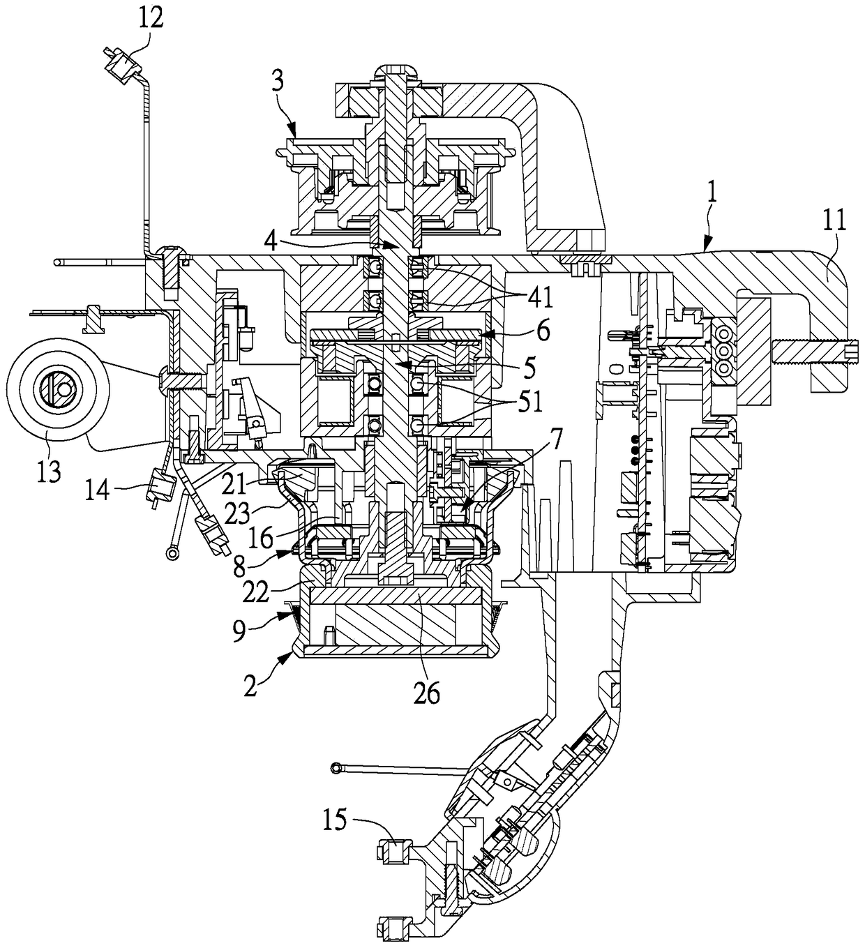
[0069] see figure 2 , The electromagnetic clutch type yarn feeding device of this embodiment includes a body 1 , a yarn storage w...

no. 2 example

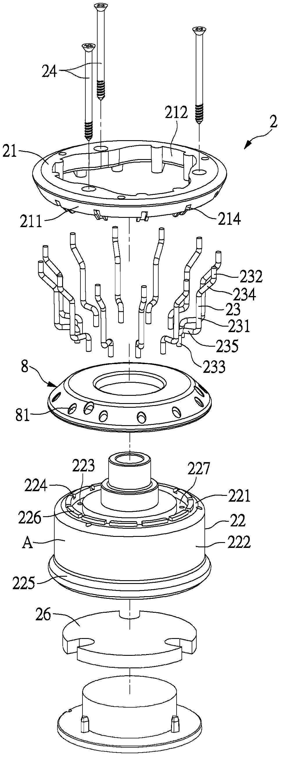
[0086] see Figure 3 to Figure 6 , the present invention additionally provides a method for assembling the yarn storage wheel of the yarn feeding device, comprising the following steps:

[0087] First, an upper wheel body 21, a lower wheel body 22, a plurality of yarn storage nails 23 and a floating disc 8 are provided; the structures of the upper wheel body 21, the lower wheel body 22, the yarn storage nails 23 and the floating disc 8 have been Described in the above-mentioned embodiment, so repeat it no longer;

[0088] Then, the floating disc 8 is placed on the top plate 221 of the lower wheel body 22, so that the perforations 81 correspond to the second insertion holes 223;

[0089] Next, insert the lower end portions 233 of the yarn storage nails 23 into the corresponding second insertion holes 223 of the lower wheel body 22 through the corresponding through holes 81; and

[0090] Then insert the upper ends 232 of these yarn storage nails 23 into the corresponding first...


PUM


Abstract

The invention discloses a yarn conveying device, a yarn storage wheel of the yarn conveying device and an assembling method of the yarn storage wheel. The yarn storage wheel of the yarn conveying device comprises an upper wheel body, a lower wheel body and multiple yarn storage nails, multiple first insertion holes are formed in the upper wheel body at intervals, the lower wheel body is provided with a top plate and a side wall, the side wall is connected to the outer edge of the top plate and extends downward, a thread winding surface is formed at the outer edge of the side wall, multiple second insertion holes are formed in the top plate at intervals, each yarn storage nail is provided with a rod body, an upper end portion and a lower end portion, the upper end portion of each yarn storage nail is arranged in the corresponding first insertion hole of the upper wheel body in an inserted mode, and the lower end portion of each yarn storage nail is arranged in the corresponding second insertion hole of the lower wheel body in an inserted mode. By means of the yarn conveying device, the yarn storage wheel of the yarn conveying device and the assembling method of the yarn storage wheel, trouble in the production inspection process can be omitted, so that man-hours are saved, and production cost is lowered.

Description

technical field [0001] The invention relates to a yarn storage wheel, in particular to a yarn feeding device, a yarn storage wheel of the yarn feeding device and an assembly method thereof, which can save the trouble of quality inspection, save man-hours and reduce production costs. Background technique [0002] The types of weaving yarns are changing with each passing day, and the demand for fabric characteristics in the weaving market is becoming more and more urgent, which makes the yarn guiding and conveying operation of the yarn feeding device more and more important. The existing yarn feeding devices are equipped with a yarn storage wheel on which the yarn can be wound, so that the belt pulley can be driven by strip elements such as a belt (not shown), and then the yarn storage wheel is driven to rotate through the transmission shaft, so that the yarn storage wheel can be used. The yarn wheel drives the yarn to store and send yarn. The existing combined yarn storage w...

Claims


Application Information

Patent Timeline
Patent Type & Authority Patents(China)
IPC IPC(8): D04B15/38D04B27/10D04B33/00
Inventor 叶紫彬叶峰富
Owner TIEN YANG KNITTING MACHINERY
Why Eureka
Try Eureka