Clamping device for roller brake of hoisting mechanism of hoist

A technology of lifting mechanism and clamping device, which is applied in hoisting device, transportation and packaging, load hanging components, etc. It can solve the problem that it is difficult to ensure that heavy objects will not fall, the clamping state of the brake is uncontrollable, and it is inconvenient to adjust, etc. problem, to achieve the effect of simple structure, controllable clamping force and easy adjustment

Active Publication Date: 2016-03-23
HENAN HENGYUAN HENGSHAN IND CO LTD
View PDF5 Cites 0 Cited by
  • Summary
  • Abstract
  • Description
  • Claims
  • Application Information

AI Technical Summary

Problems solved by technology

[0002] For production cranes, electric brakes are currently used for the braking of the drum, and when the drum needs to be stopped, the brake shoes are used to stop the drum from working. There are certain disadvantages in the existing brake, mainly in the following aspects: The brake needs to clamp the brake shoes under the action of external force to stop the drum normally. When the external force drive device is in the power-off state, the lower side cannot normally control the start and stop of the drum. In this way, when the drum lifts heavy objects, if the brake suddenly loses power , it is difficult to ensure that heavy objects will not fall, and may even cause accidents. In addition, the brakes set on the outer wall of the drum are not easy to adjust, so that the clamping state of the brakes is uncontrollable

Method used


Image

  • Clamping device for roller brake of hoisting mechanism of hoist
  • Clamping device for roller brake of hoisting mechanism of hoist
  • Clamping device for roller brake of hoisting mechanism of hoist

Examples


Embodiment 1

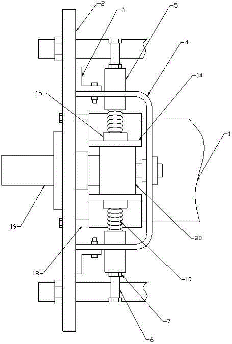
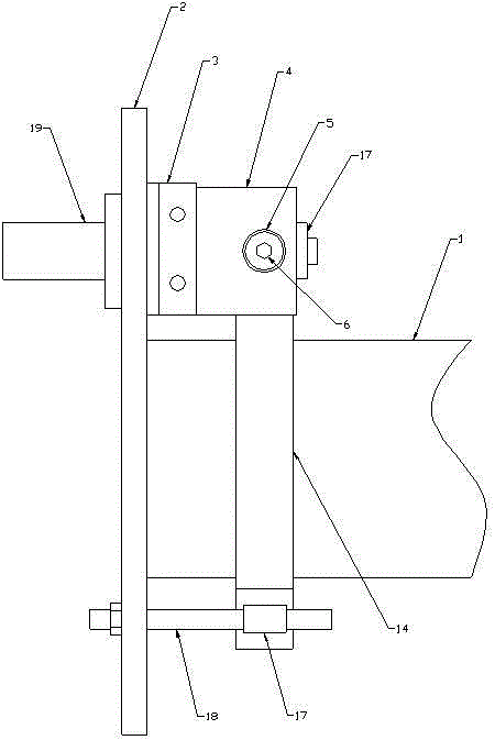
[0026] Such as Figure 1-8 As shown, a clamping device for a drum brake of a crane hoisting mechanism, which includes a drum 1, one end of the drum 1 is provided with a fixed plate 2, and the upper right side of the fixed plate 2 is provided with a connecting plate 3. The connecting plate 3 is connected with a U-shaped bracket 4 by bolts, a spring support 5 is embedded on the side wall of the U-shaped bracket 4, and one end of the spring support 5 is threadedly connected Rod 6, the outer wall of the threaded rod 6 is sleeved with a nut 7, the outer surface of the other end of the spring support 5 is provided with threads, the spring support 5 is threadedly connected with an adjustment ring 8 and a fixed ring 9, the spring support A spring base 24 and a spring 10 matched with the spring base 24 are sequentially arranged in the seat 5 from the inside to the outside, and the spring base 24 includes a limit ring 11 and a boss 12 connected to the center of one side of the limit rin...

Embodiment 2

[0029] Such as Figure 1-8 As shown, a clamping device for a drum brake of a crane hoisting mechanism, which includes a drum 1, one end of the drum 1 is provided with a fixed plate 2, and the upper right side of the fixed plate 2 is provided with a connecting plate 3. The connecting plate 3 is connected with a U-shaped bracket 4 by bolts, a spring support 5 is embedded on the side wall of the U-shaped bracket 4, and one end of the spring support 5 is threadedly connected Rod 6, the outer wall of the threaded rod 6 is sleeved with a nut 7, the outer surface of the other end of the spring support 5 is provided with threads, the spring support 5 is threadedly connected with an adjustment ring 8 and a fixed ring 9, the spring support A spring base 24 and a spring 10 matched with the spring base 24 are sequentially arranged in the seat 5 from the inside to the outside, and the spring base 24 includes a limit ring 11 and a boss 12 connected to the center of one side of the limit rin...


PUM


Abstract

The invention relates to a clamping device for a roller brake of a hoisting mechanism of a hoist. The clamping device comprises a roller, wherein a fixing plate is arranged at one end of the roller; connecting plates are arranged on the right side face of the upper portion of the fixing plate and connected with a U-shaped support through bolts; a spring supporting seat is embedded in the side wall of the U-shaped support; one end of the spring supporting seat is connected with a threaded rod through screw threads; the other end of the spring supporting seat is connected with an adjusting ring and a fixing ring through screw threads; a spring base and a spring are arranged sequentially from inside to outside in the spring supporting seat; the other end of the spring is connected with a brake shoe; a spring casing is welded on the outer side face of the upper end of the brake shoe; a pressure sensor is arranged at the bottom of the spring casing; a fixing casing is welded on the outer side of the lower end of the brake shoe; a fixing shaft is arranged inside the fixing casing; a cam shaft is arranged between the fixing plate and the U-shaped support; the outer wall of the right portion of the cam shaft is sleeved with a cam matched with the brake shoe. The clamping device has the following advantages: the structure is simple; usage and adjustment are convenient; the clamping force can be controlled.

Description

technical field [0001] The invention belongs to the technical field of crane drum braking equipment, in particular to a clamping device for a drum brake of a crane hoisting mechanism. Background technique [0002] For production cranes, electric brakes are currently used for the braking of the drum, and when the drum needs to be stopped, the brake shoes are used to stop the drum from working. The existing brakes have certain disadvantages, mainly in the following aspects: The brake needs to clamp the brake shoes under the action of external force to stop the drum normally. When the external force drive device is in the power-off state, the lower side cannot normally control the start and stop of the drum. In this way, when the drum lifts heavy objects, if the brake suddenly loses power , it is difficult to ensure that heavy objects will not fall, and may even cause accidents. In addition, the brakes arranged on the outer wall of the drum are not easy to adjust, so that the c...

Claims


Application Information

Patent Timeline
Patent Type & Authority Applications(China)
IPC IPC(8): B66D5/08B66C13/16
CPCB66C13/16B66D5/08
Inventor 陶和平乾红伦戚良才马建良任伟杰
Owner HENAN HENGYUAN HENGSHAN IND CO LTD
Why Eureka
Try Eureka