
Laser connection method based on laser material additive manufacturing technology

A technology of laser additive manufacturing technology, applied in the field of material processing, which can solve the problems of metallurgical incompatibility, singular stress behavior, structural integrity and reliability effects, etc., to achieve improved tunability, high heating and cooling speed, the effect of improving connection quality

Inactive Publication Date: 2016-03-23
HARBIN INST OF TECH
View PDF7 Cites 24 Cited by
  • Summary
  • Abstract
  • Description
  • Claims
  • Application Information

AI Technical Summary

Problems solved by technology

However, due to the huge differences in the physical, chemical and mechanical properties of dissimilar materials, the requirements for the connection method are relatively strict, and there are: metallurgical incompatibility, brittle compound phases formed at the interface, residual stress due to mismatching of thermophysical properties, and mechanical properties. The huge difference in performance leads to mechanical mismatch at the connection interface, resulting in serious stress singular behavior, etc.; these problems make the connection of dissimilar materials difficult, and affect the joint organization, performance and mechanical behavior, and the integrity and reliability of the structure will be seriously affected

Method used


Image

  • Laser connection method based on laser material additive manufacturing technology
  • Laser connection method based on laser material additive manufacturing technology
  • Laser connection method based on laser material additive manufacturing technology

Examples


specific Embodiment approach 1

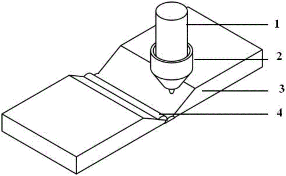
[0027] Specific Embodiment One: A laser connection method based on laser additive manufacturing technology in this embodiment is carried out in accordance with the following steps:

[0028] 1. Before welding, process the groove of the workpiece to be welded, and at the same time, grind and clean the processed groove and the surface of the workpiece, and fix the polished and cleaned workpiece to be welded on the welding fixture;

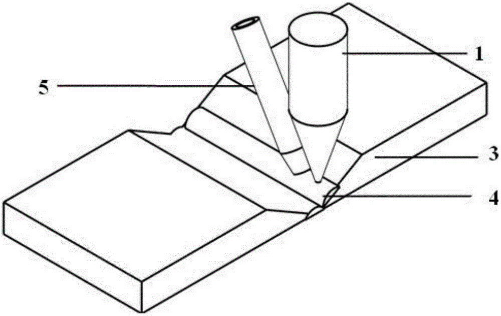
[0029] 2. During the connection process based on laser additive manufacturing using side-axis powder feeding, the laser head and side-axis powder feeding working head are fixed on the joint area to be connected by using a fixture, and the angle between the powder feeding head and the vertical direction is adjusted to 10°~80°;

[0030] If the material to be connected is non-reflective to the laser, keep the laser head vertical to the workpiece to be welded, adjust the angle between the side axis powder feeding head and the laser head to 10°-80°, and ke...

specific Embodiment approach 2

[0034]Embodiment 2: The difference between this embodiment and Embodiment 1 is that the laser emitting laser is a fiber laser, a YAG solid-state laser, a semiconductor laser or a CO 2 laser. Others are the same as in the first embodiment.

specific Embodiment approach 3

[0035] Embodiment 3: This embodiment differs from Embodiment 1 in that the cleaning described in step 1 is carried out with acetone, or other cleaning methods for removing oil stains and oxide film impurities on the material surface. Others are the same as in the first embodiment.

[0036] Specific embodiment three: the difference between this embodiment and specific embodiment one is: if the material to be connected is a material that does not reflect the laser, then keep the laser head and the workpiece to be welded vertically, and adjust the side axis powder feeding working head and the laser head The included angle is 20°~70°, and the distance between the powder feeding nozzle and the laser focal plane is 3~19mm. Others are the same as in the first embodiment.


PUM


Abstract

A laser connection method based on the laser material additive manufacturing technology relates to a welded connection method of a special material. According to the laser material additive manufacturing principle, and by utilizing the laser depositing method and the layer-by-layer piling method, a new material shaped like the welding seam between two base materials is formed between the welding seam of two connecting materials and the formed new material is further utilized to connect the two base materials. According to the laser connection method based on the laser material additive manufacturing technology, provided by the invention, the metallurgical composition of the welding seam and the joint performance are improved, near-net forming connection is realized, materials are greatly saved, the cost is reduced, weld defects are controlled, the degree of automation is high, and the operation is easy; besides, a fiber laser, a YAG solid laser, a semiconductor laser or CO2 laser are taken as the core, and a powder feed device, a protective gas system and a cooling system are taken as auxiliary appliances, therefore the overall system is high in automation level, can realize whole-process computer control, and is simple in operation processes and further easy to implement.

Description

technical field [0001] The invention relates to a laser connection method based on laser additive manufacturing technology, which belongs to the field of material processing. Background technique [0002] The concept of additive manufacturing technology was first proposed in the late 1970s to early 1980s, which included dozens of molding processes such as Selective Laser Sintering (SLS), Laminated Object Manufacturing (LOM), and more. "Time" magazine listed additive manufacturing technology as "the ten fastest-growing industries in the United States"; the British "Economist" believes that "additive manufacturing technology will promote the third industrial revolution and will also change the production organization model". Both the world's scientific and technological powers and emerging countries will cultivate and support additive manufacturing technology as a new growth point for future industrial development, so as to seize the commanding heights of the future technologi...

Claims


Application Information

Patent Timeline
Patent Type & Authority Applications(China)
IPC IPC(8): B23K26/26B23K26/60B23K26/144
CPCB23K26/26
Inventor 陈彦宾李鹏陈曦雷正龙张可召张恒泉
Owner HARBIN INST OF TECH
Learn More