Drain device

A technology for drainage equipment and wastewater, applied in drainage structures, waterway systems, water supply devices, etc., can solve problems such as increasing cleaning work and increasing cleaning costs, and achieve the effect of preventing reproduction, reducing cleaning work and cleaning costs, and being technically simple.

Inactive Publication Date: 2016-03-16
ACO SEVERIN AHLMANN GMBH & CO KG
View PDF10 Cites 2 Cited by
  • Summary
  • Abstract
  • Description
  • Claims
  • Application Information

AI Technical Summary

Problems solved by technology

This results in increased cleaning effort and increased cleaning costs

Method used


Image

  • Drain device
  • Drain device
  • Drain device

Examples


Embodiment Construction

[0024] In the following description, the same reference numerals will be used for the same and same acting parts.

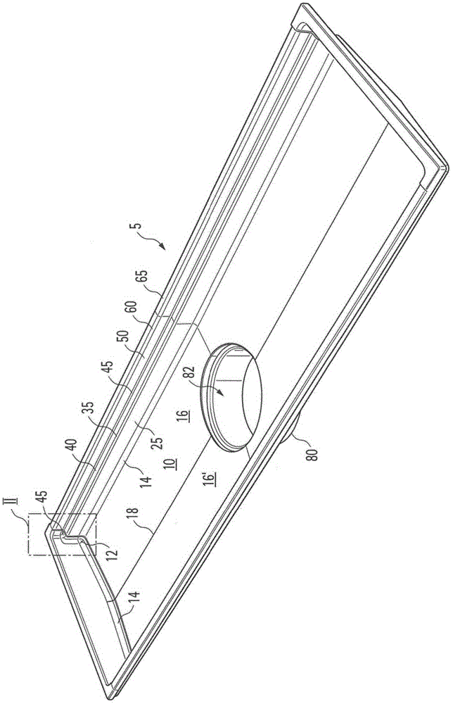
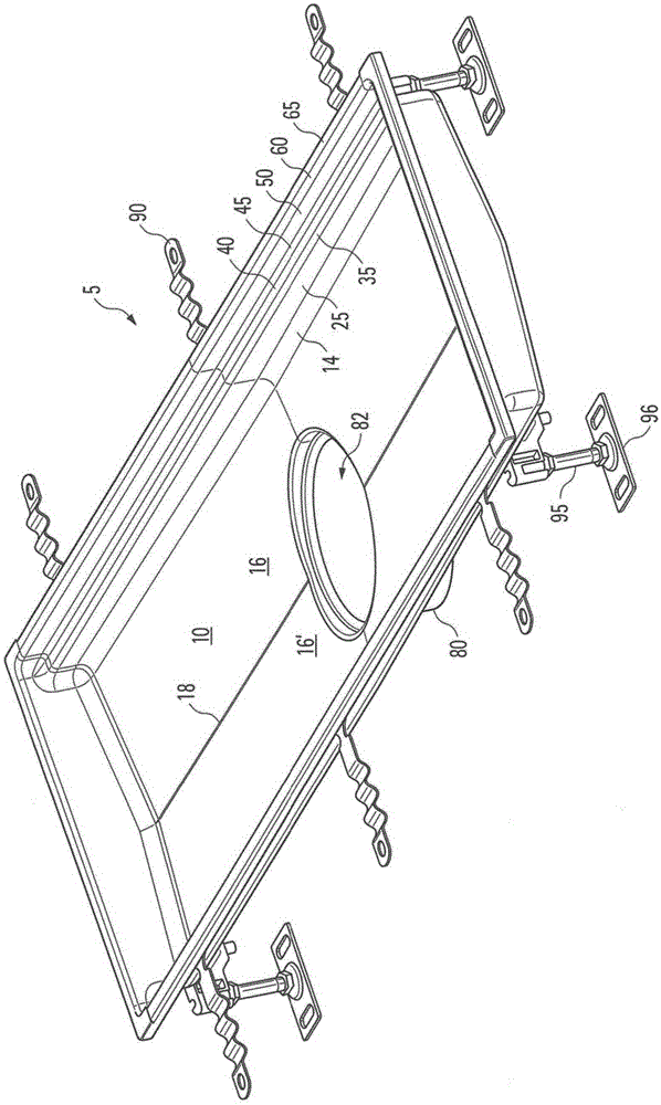
[0025] figure 1 A perspective x-ray view of a first embodiment of a drainage device 5 according to the invention is shown. The drainage device 5 is, for example, a drainage channel installed in the bottom, for example the tile bottom. However, it is also conceivable that the drain device 5 is a shower drain. The drainage device 5 can also be a sewer element.

[0026] The drainage device 5 comprises a bottom 10 . Waste water collects on the bottom 10 and is conveyed into the opening 82 of the outlet 80 . The outlet 80 is used to connect the drainage device 5 to a sewer pipe or sewer system.

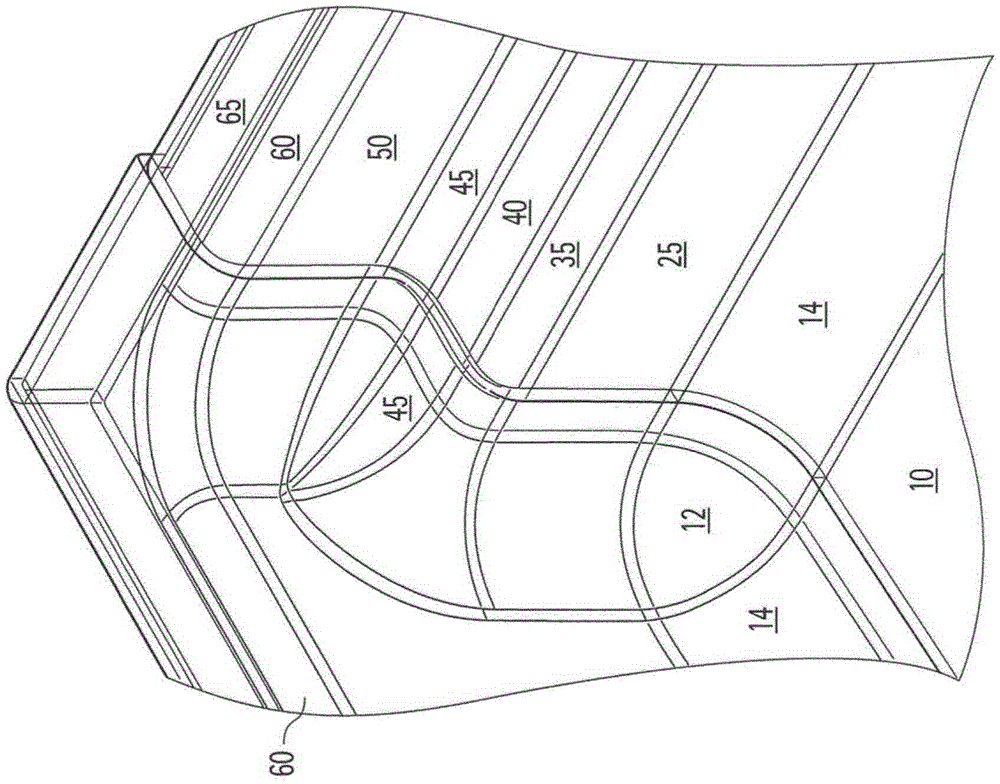
[0027] figure 2 show figure 1 Detail view of Region II. The bottom 10 adjoins the outer edge 14 and the corner 12 . The outer edge 14 is rounded. The corners 12 are likewise of rounded design.

[0028] Drainage device 5 is comprised on two opposite longitudinal si...


PUM


Abstract

The invention relates to a drain device (5) for discharging waste water, having an upper edge surface (65) forming an outer perimeter of the drain device (5), a support surface (40) for supporting a cover member such that essentially, the walkable surface thereof extends flush with the upper edge surface (65), and having a bottom (10) for catching, and for conveying waste water to an opening (82) of an outflow connecting pipe (80). The upper edge surface (65), the support surface (40), and the bottom (10) are connected to one another by way of connection walls (25, 50) extending essentially vertically when in use. At least one part of the support surface (40) is formed in a sloping manner in the direction of the bottom (10) such that during use, waste water, which reaches the support surface (40), flows in the direction of the bottom (10).

Description

technical field [0001] The invention relates to a drainage installation according to claim 1 . Background technique [0002] Various drainage devices are known for treating wastewater. One problem with hitherto known drainage installations is that waste water accumulates or remains on the various surfaces of the drainage installation, in particular on the support surfaces used to support the covering elements. Instead of runoff, wastewater that remains on the surface evaporates for any amount of time. As a result, the humidity increases and the evaporated wastewater leaves a residue on the surface of the drainage. This results in increased cleaning effort and increased cleaning costs. In addition, bacteria multiply very rapidly in wastewater held on surfaces. This threatens the health of people who come into contact with waste water that remains on surfaces, or who inhale waste water that evaporates after a certain time. Contents of the invention [0003] The inventio...

Claims


Application Information

Patent Timeline
Patent Type & Authority Applications(China)
IPC IPC(8): E03F5/04
CPCE03F5/0408E03F2005/0413Y02A30/60Y10T137/5762E03F5/04
Inventor 伊沃·涅梅茨
Owner ACO SEVERIN AHLMANN GMBH & CO KG
Why Eureka
Try Eureka