Surgical clip, in particular aneurysm clip

A clamp and surgical technology, which is applied in medical science, wound clips, surgery, etc., can solve the problems that the clamp arm cannot be opened and closed in a parallel manner, and the closing force is reduced, and achieves large spring force, small installation space, The effect of avoiding destruction

Active Publication Date: 2016-03-16
AESCULAP AG
View PDF4 Cites 1 Cited by
  • Summary
  • Abstract
  • Description
  • Claims
  • Application Information

AI Technical Summary

Problems solved by technology

[0008] Since the frame spring is usually arranged asymmetrically with respect to the branch of the clamp or its clamping arm, frictional forces can disadvantageously occur between the branch or clamping arm and the spring leg cooperating with it
This results in a reduction in th

Method used


Image

  • Surgical clip, in particular aneurysm clip
  • Surgical clip, in particular aneurysm clip
  • Surgical clip, in particular aneurysm clip

Examples


Embodiment Construction

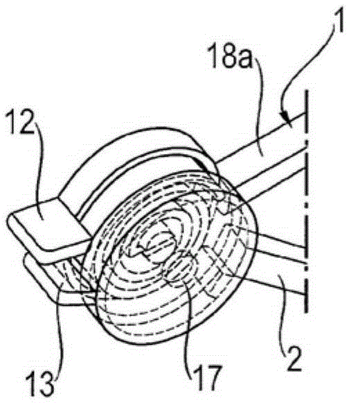
[0032] figure 1 and 2 The illustrated surgical clamps are represented in partial cross-section or partially disassembled illustrations. Thus, the pliers comprise two jaw parts (jaw part halves), namely a first jaw part 15 comprising a first clamping arm (or branch) 1 and a second jaw part comprising a second clamping arm (or branch) 2 Part 16. The two jaw parts 15 and 16 and thus the clamping arm 1 and the clamping arm 2 are coupled to each other in a rotatable or pivotable manner and are preloaded against each other in the rotational direction by means of the spring 4 towards the closed clamping position . figure 1 as well as Figure 3c The clamps in are shown in the position in which clamping arms 1 and 2 are pressed against each other with the required clamping force. The clamping force acting between clamping arms 1 and 2 is at figure 1 Arrow F K1 and F K2 instruct. The clamping arms 1 and 2 are respectively elongated and comprise flat clamping surfaces 18a, b whi...


PUM


Abstract

The invention relates to a surgical clip with a first clipping arm (1) and a second clipping arm (2), which are coupled together so that they can rotate and are stressed counter to each other, in the direction of rotation, in a closed position by means of a spring (4). A first housing section (5) is embodied or arranged on the first clipping arm (1) and a second housing section (6) is embodied or arranged on the second clipping arm (2), a housing (7) being formed in the housing sections (5,6) in which the spring (4) is received.

Description

technical field [0001] The present invention relates to surgical clamps, in particular aneurysm clamps, comprising a first clamping arm or jaw part and a second clamping arm or jaw part, said clamping arms or jaw parts being rotatably coupled to each other by means of a hinge and They are prestressed against each other in the rotational direction by means of springs into the closed position. Background technique [0002] Surgical clips are medical devices or implants that are used temporarily to clip or close holes in tissue or as vascular clips for long-term medical care such as aneurysms. Many different jaws are known, for example in the form of jaw jaws, in which the grip or jaw branches are formed so as to bend in the longitudinal direction in a similar manner to the upper and lower jaws and to be hinged at their two ends to each other. coupling. Another example is represented by slender, elongated pliers similar to conventional pliers, comprising two opposing gripping...

Claims


Application Information

Patent Timeline
IPC IPC(8): A61B17/122A61B17/00
CPCA61B17/1227A61B2017/00685
Inventor 格罗尔德·齐里斯科尔温·莫茨乔基姆·亚曼
Owner AESCULAP AG
Why Eureka
Try Eureka