Motor carbon brush assembly with stable brush pressure

A carbon brush and component technology, applied in electrical components, motor generator connectors, circuits, etc., can solve the problems of rising motor current value, easy generation of sparks, and unstable current, so as to avoid excessive wear of carbon brushes and reduce sparks. The effect of producing and increasing the service life

Inactive Publication Date: 2016-03-16
TONGXIANG LISHAN IND CO LTD
View PDF6 Cites 0 Cited by
  • Summary
  • Abstract
  • Description
  • Claims
  • Application Information

AI Technical Summary

Problems solved by technology

[0003] Traditionally, in order to maintain electrical contact between the carbon brush holder and the commutator of the series motor, a coil spring is usually installed on the rear end surface of the carbon brush holder, and the carbon The front face of the brush pushes against the outer periphery of the commutator. Since the elastic force of the coil spring is related to its compression deformation, the compression deformation of the coil spring is relatively large at the initial stage of carbon brush use (when the length of the carbon brush is long). At this time, the elastic value of the coil spring applied to the carbon brush is also large. Then, when the carbon brush wears for a period of time, because the length of the carbon brush becomes shorter, the compression deformation of the coil spring is small. At this time, the coil spring applies to the carbon brush. The elastic force value will also be small. In other words, the brush pressure at the initial stage of carbon brush use and the brush pressure at the end of wear will be different, and a larger brush pressure will cause the current value of the motor to increase, and the wear of the carbon brush and commutator increase, and a smaller brush voltage will cause the current to be unstable and sparks are likely to occur

Method used


Image

  • Motor carbon brush assembly with stable brush pressure
  • Motor carbon brush assembly with stable brush pressure
  • Motor carbon brush assembly with stable brush pressure

Examples


Embodiment Construction

[0022] The present invention will be further described in detail below in conjunction with the accompanying drawings and examples. The following examples are explanations of the present invention and the present invention is not limited to the following examples.

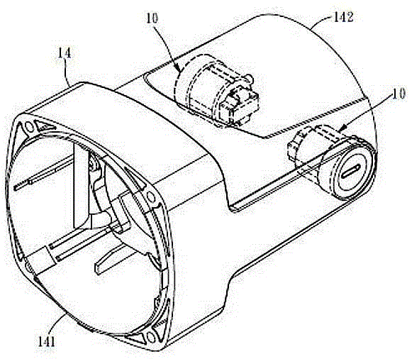
[0023] Such as figure 1 As shown, the motor carbon brush assembly 10 with stable brush pressure is arranged on the inner surface of a motor housing 14. The motor housing 14 is elongated and has an open end 141 and a closed end 142 separated by a considerable distance. There are two motor carbon brush holders 10 at opposite positions, and the installation positions of each motor carbon brush holder 10 are quite close to the closed end 142 .

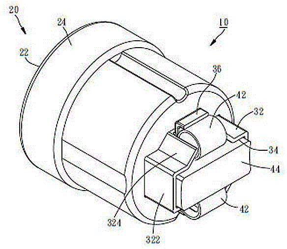
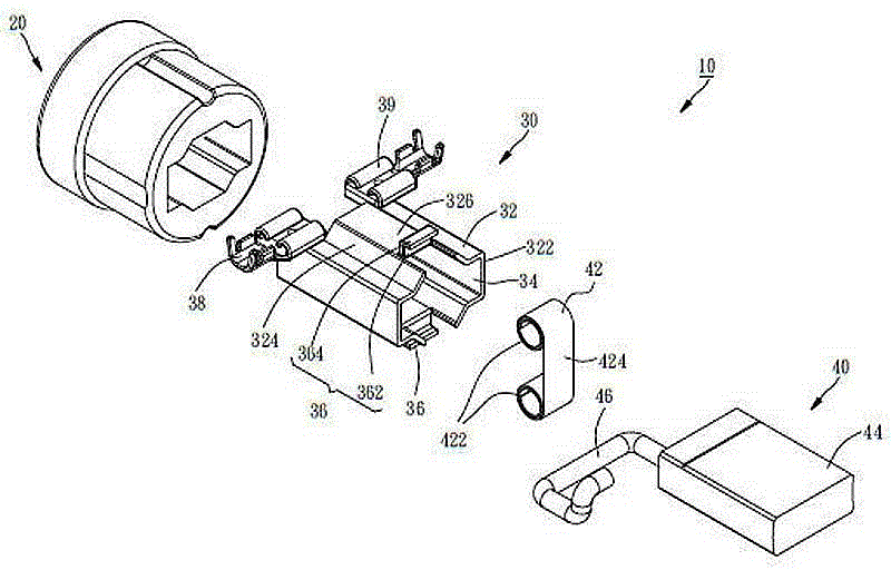
[0024] Such as figure 2 with image 3 , the motor carbon brush holder 10 is mainly composed of an insulating case 20, a conductive member 30, and a carbon brush assembly 40, wherein:

[0025] The insulating case 20 is made of insulating material (such as Bakelite), has a bot...


PUM


Abstract

The invention provides a motor carbon brush assembly with stable brush pressure, and belongs to the technical field of motors. The motor carbon brush assembly comprises an insulating shell, a conductive part and a carbon brush assembly, wherein the conductive part comprises a pipe body and a carbon brush slide chute; one part of the pipe body is arranged in the insulating shell; the carbon brush slide chute is located at the inner side of the pipe body; the carbon brush assembly comprises a constant-force spring and a carbon brush; the constant-force spring comprises two coiled segments and a straight segment; the straight segment is located between the two coiled segments; the two coiled segments are arranged at the outer side of the front end of the pipe body of the conductive part respectively; the straight segment spans an opening of the carbon brush slide chute of the conducive part and is propped against the rear end surface of the carbon brush; and the carbon brush is arranged in the carbon brush slide chute of the conductive part in a slideable penetrating manner and is electrically connected to the conductive part. According to the motor carbon brush assembly, the stable brush pressure can be kept between the carbon brush and a communtator; sparks can be effectively reduced; and excessive abrasion of the carbon brush caused by over-large brush pressure can also be avoided, so that the service lifetime of a motor carbon brush holder is prolonged.

Description

technical field [0001] The invention relates to the technical field of motors, in particular to a motor carbon brush assembly with stable brush pressure. Background technique [0002] Generally, the operating efficiency and service life of series motors are mostly related to the stability of carbon brush pressure and the degree of carbon brush wear. Therefore, a well-designed carbon brush holder structure can not only provide stable brush pressure, but also reduce carbon brush pressure. Wear and tear of the commutator, thereby improving the efficiency and service life of the motor, and reducing the frequency of maintenance and replacement. [0003] Traditionally, in order to maintain electrical contact between the carbon brush holder and the commutator of the series motor, a coil spring is usually installed on the rear end surface of the carbon brush holder, and the carbon The front face of the brush pushes against the outer periphery of the commutator. Since the elastic fo...

Claims


Application Information

Patent Timeline
IPC IPC(8): H01R39/415
CPCH01R39/381H01R39/415H01R2201/10
Inventor 赖澄渊
Owner TONGXIANG LISHAN IND CO LTD
Why Eureka
Try Eureka