Underwater electromagnetic separation component and underwater electromagnetic separation device

An electromagnetic separation and separation device technology, applied in electrical components, coupling devices, connecting device components and other directions, can solve the problems of high cost, reduce the electromagnetic force of the electromagnetic separation mechanism, prone to separation failure, etc. Gap length, the effect of guaranteeing the service life

Inactive Publication Date: 2018-05-22
CHINA AVIATION OPTICAL-ELECTRICAL TECH CO LTD
View PDF3 Cites 0 Cited by
  • Summary
  • Abstract
  • Description
  • Claims
  • Application Information

AI Technical Summary

Problems solved by technology

[0003] The existing problem of this underwater electromagnetic separation device is: in order to make the mandrel sleeve move to the left, the lock ball can fall into the lock groove of the mandrel sleeve, and the mandrel sleeve must be able to move at least one lock. The diameter distance of the ball, that is to say the air gap between the fixed iron core and the moving iron core is the diameter of at least one lock ball, while the diameter of the lock ball in the prior art is 3.5mm, so the fixed iron core and the moving iron core The air gap between them is at least 3.5mm. Such a large air gap reduces the electromagnetic force of the electromagnetic separation mechanism. When the underwater depth increases, the length of the power supply cable increases, and the cable resistance increases. Under the same voltage, The separation voltage received by the electromagnetic separation mechanism is reduced, so that when the water depth exceeds 10 meters, the separation failure problem is prone to occur due to the small voltage of the power supply cable, which cannot meet the needs of weapon development; the supply cable is vulcanized and fixed on the separation device shell, That is to say, the length of the supply cable cannot be changed under normal circumstances. When the water depth conditions of the projectile body change, the length of the supply cable cannot meet the requirements, and it is necessary to remove the supply cable from the inside of the separation device housing and re-vulcanize. This process is very troublesome and costly; because the supply cable needs to be vulcanized, the supply cable and the signal transmission cable are in an independent state. The signal transmission cable and the supply cable cannot be combined for watertight treatment, and the supply cable and signal transmission are required. Cables are laid out separately, and the process of laying out cables is also relatively cumbersome

Method used


Image

  • Underwater electromagnetic separation component and underwater electromagnetic separation device
  • Underwater electromagnetic separation component and underwater electromagnetic separation device

Examples


Embodiment Construction

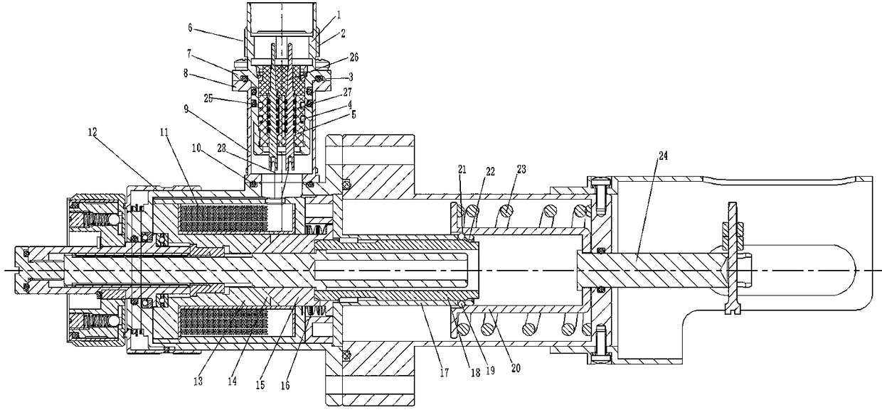
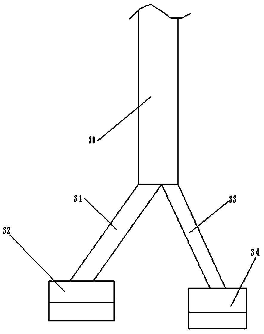
[0023] Examples of underwater electromagnetic separation device components are Figure 1~2 Shown: include power supply cable 31, signal transmission cable 33 and underwater electromagnetic separation device, underwater electromagnetic separation device includes the separation device shell 12 that is provided with electromagnetic separation mechanism inside, for the main part of cable 31, signal transmission cable 33 wears Set in the same cable sheath 30, the end of the power supply cable 31 is provided with a power supply plug 32, and the end of the signal transmission cable 33 is provided with a signal plug 34, that is to say, the power supply cable and the signal transmission cable belong to the same hybrid cable. When stripping the cable sheath end of the hybrid cable, the power supply cable and the signal transmission cable are separated. The electromagnetic separation mechanism includes an electromagnetic coil 11, a fixed iron core 13 and a moving iron core 15 that can gu...


PUM


Abstract

The invention relates to an underwater electromagnetic separating assembly and an underwater electromagnetic separating apparatus therefor. The underwater electromagnetic separating apparatus comprises a separating apparatus shell, wherein an electromagnetic separating mechanism is arranged in the separating apparatus shell; the electromagnetic separating mechanism comprises electromagnetic coils, a fixed iron core and a mobile iron core; a limiting sleeve is fixedly arranged on the separating apparatus shell; a mandrel sleeve penetrating through the limiting sleeve is arranged on the mobile iron core; a separating sleeve capable of moving left and right is arranged on the exterior of the limiting sleeve in a sleeving manner; a plurality of radically-floating lock balls are arranged on the limiting sleeve at intervals around the axial direction; mandrel sleeve locking grooves matched with the inner ends of the lock balls are formed in the mandrel sleeve; separating sleeve lock grooves matched with the outer ends of the lock balls are formed in the separating sleeve; the diameter of the each lock ball is 1.5-2.5 mm; and the air gap between the mobile iron core and the fixed iron core is 1.5-2.5 mm. According to the underwater electromagnetic separating apparatus and the underwater electromagnetic separating apparatus assembly using the underwater electromagnetic separating apparatus provided by the invention, the air gap between the mobile iron core and the fixed iron core can be reduced.

Description

technical field [0001] The invention relates to an underwater electromagnetic separation component and an underwater electromagnetic separation device thereof. Background technique [0002] The underwater electromagnetic separation device is used for launching underwater projectiles. The existing underwater electromagnetic separation device, such as "a kind of underwater electromagnetic separation device" disclosed in Chinese patent CN103904475A, includes a separation device housing, and the separation device housing is set There is an electromagnetic separation mechanism. The electromagnetic separation mechanism includes an electromagnetic coil and a moving iron core that can guide and move along the left and right directions. A limit sleeve is fixed in the shell of the separation device. The mandrel sleeve, the corrugated spring is set on the top between the moving iron core and the limit sleeve, and the separation sleeve is also guided and moved along the left and right d...

Claims


Application Information

Patent Timeline
Patent Type & Authority Patents(China)
IPC IPC(8): H01R13/635
CPCH01R13/635
Inventor 卞书波
Owner CHINA AVIATION OPTICAL-ELECTRICAL TECH CO LTD
Why Eureka
Try Eureka