Gas headwind injection gas mixing combustor

A gas burner and headwind technology, which is applied in the direction of gas fuel burners, burners, and combustion methods, can solve the problems of poor mixing effect of gas and air, poor combustion safety of gas burners, and large mixing space structure. , to achieve the effect of shortening the length, improving safety and improving combustion efficiency

Inactive Publication Date: 2016-03-16
YUNNAN AEROSPACE IND
View PDF5 Cites 6 Cited by
  • Summary
  • Abstract
  • Description
  • Claims
  • Application Information

AI Technical Summary

Problems solved by technology

[0003] Gas burners on the market are mostly arranged along the direction of wind flow velocity, so the mixing effect of gas and air is not good; and the mixing space structure is relatively large, so the combustion safety of gas burners is poor

Method used


Image

  • Gas headwind injection gas mixing combustor

Examples


Embodiment Construction

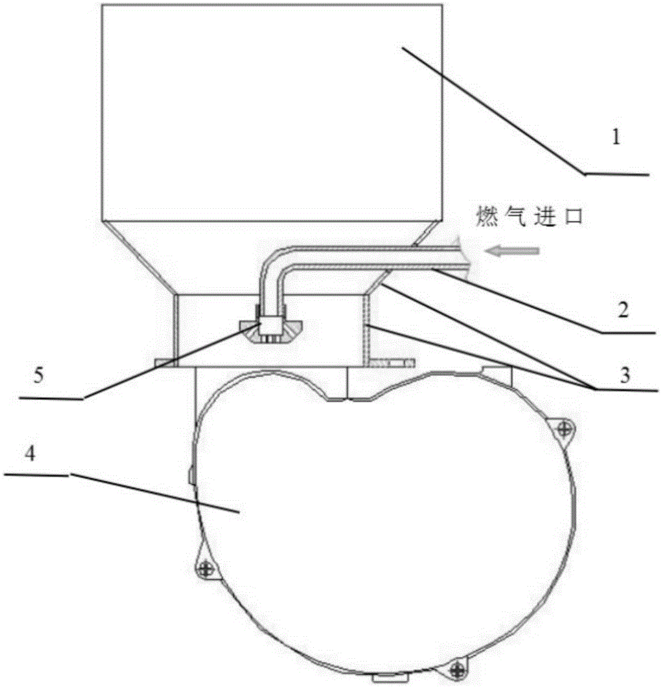
[0012] See figure 1 , a kind of gas upwind injection mixed gas burner, comprising a combustion head 1, a gas pipe 2, an air duct 3, a fan 4 and a spray nozzle 5; The combustion head 1 and the gas pipe 2 pass through the wall of the air cylinder and enter the air cylinder 3, the nozzle 5 is connected to the outlet of the gas pipe, the outlet of the gas pipe 2 is downward, and the gas sprayed by the nozzle is opposite to the direction of the wind.

[0013] The gas pipe of the present invention is a single outlet, and may also be a plurality of outlets.


PUM


Abstract

The invention discloses a gas headwind injection gas mixing combustor. The combustor comprises a burning head, a gas pipe, an air cylinder, a fan and a nozzle, and is characterized in that the lower end of the air cylinder is connected with the fan; the upper end of the air cylinder is connected with the burning head; the gas pipe penetrates through the wall of the air cylinder to enter the air cylinder; the nozzle is connected to an outlet end of the gas pipe; an outlet of the gas pipe is downwards; and gas injected by the nozzle is opposite to the wind direction. The gas headwind injection gas mixing combustor has the following beneficial effects: the fuel and air mixing effect is intensified to improve the combustion efficiency; and the length of a mixed gas pipeline is shortened to improve the safety of the gas combustor.

Description

technical field [0001] The invention belongs to the technical field of gas burners. Background technique [0002] For gas burners, whether the mixing of gas and air before combustion is sufficient or not is a very important reason that affects the combustion effect. Insufficient mixing will have disadvantages such as insufficient combustion, unstable combustion, loud combustion noise, and high pollutant emissions. At the same time, the size of the mixing space is also an important factor affecting the safety of the gas burner. In order to improve safety, the size of the mixing space should be reduced as much as possible. Therefore, the design of the burner should minimize the size of the mixing space on the premise of ensuring that the gas and air are fully mixed. [0003] The gas burners on the market are mostly arranged along the direction of the wind flow velocity, so the mixing effect of gas and air is not good; and the mixing space structure is relatively large, so th...

Claims


Application Information

Patent Timeline
IPC IPC(8): F23D14/02F23D14/58
CPCF23D14/02F23D14/58
Inventor 陈令清刘世青陈丹
Owner YUNNAN AEROSPACE IND
Why Eureka
Try Eureka