Oxygen-complementing type air-hydrogen/air-oxygen pneumatic resonance heat surface igniter

An oxygen dynamic resonance and igniter technology, which is applied in the direction of machines/engines, jet propulsion devices, rocket engine devices, etc., can solve problems such as limiting the ignition ability of the igniter, thin walls are easy to be burned, and the ignition ability of the resonance igniter is difficult to meet the requirements. Achieve low cost and improve the effect of hydrogen-oxygen blending

Inactive Publication Date: 2010-04-28
BEIHANG UNIV
View PDF0 Cites 10 Cited by
  • Summary
  • Abstract
  • Description
  • Claims
  • Application Information

AI Technical Summary

Problems solved by technology

However, common pneumatic resonant igniters also have some shortcomings. Under the requirements of large flow of hydrogen and high ignition energy, the thin wall between the exhaust holes of the mixing cup is easy to be burned, which limits the ignition ability of the igniter.
The scramjet ground test system needs to heat a large flow of air, and the ignition capacity of ordinary resonance igniters is difficult to meet the requirements. The aerodynamic resonance hot surface oxygen supplement igniter relies on the cooperation of the oxygen supply nozzle and the aerodynamic resonance thermal effect, which greatly improves the ignition efficiency. The ignition capability and reliability of the engine have been successfully applied to the scramjet ground test system

Method used


Image

  • Oxygen-complementing type air-hydrogen/air-oxygen pneumatic resonance heat surface igniter
  • Oxygen-complementing type air-hydrogen/air-oxygen pneumatic resonance heat surface igniter
  • Oxygen-complementing type air-hydrogen/air-oxygen pneumatic resonance heat surface igniter

Examples


Embodiment Construction

[0013] The present invention will be further described below in conjunction with the accompanying drawings.

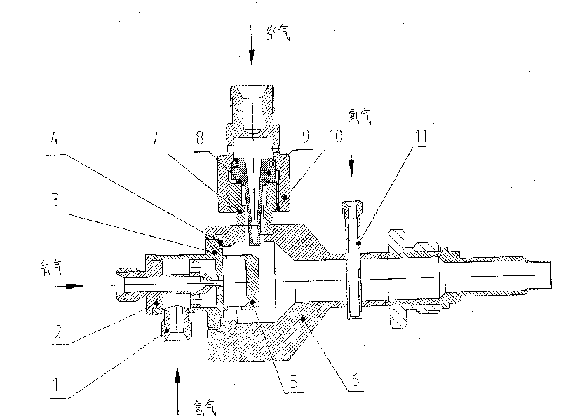
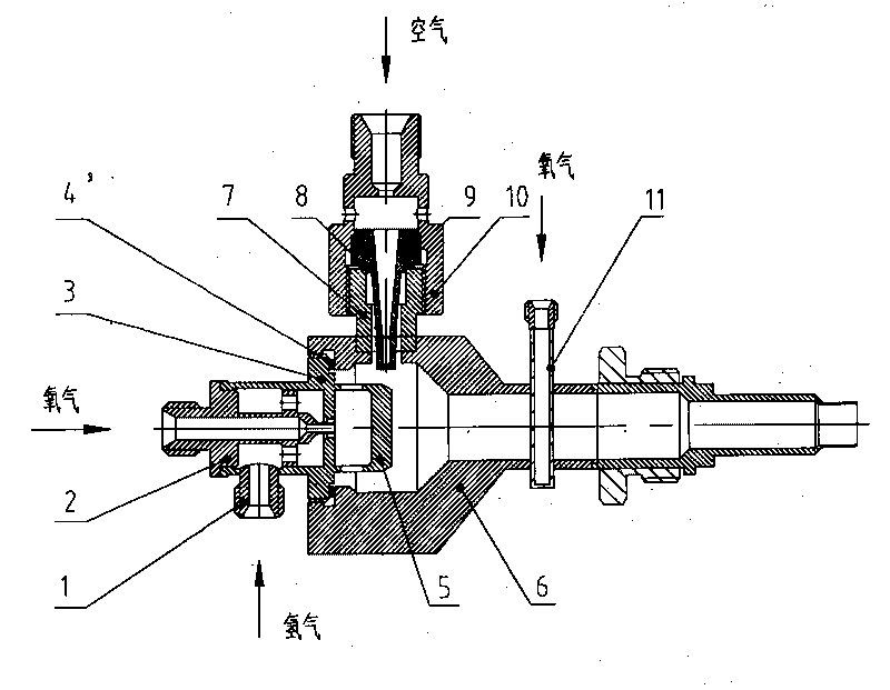
[0014] Such as figure 1 As shown, the structure of the oxygen-supplementing gas-hydrogen / gas-oxygen dynamic resonance thermal surface igniter consists of a hydrogen nozzle 1, an oxygen nozzle 2, a nozzle 3, a sealing gasket 4, a mixing cup 5, an ignition chamber 6, a resonance pipe nozzle 7, The resonance tube adjustment gasket 8, the resonance tube 9, the air nozzle 10, and the oxygen supplement nozzle 11 are composed.

[0015] The oxygen nozzle 2 is located at the center of the nozzle 3 and is a channel for oxygen, and the two are connected by welding. The hydrogen nozzle 1 is welded on the side of the nozzle 3, and the hydrogen gas enters the nozzle 3 through the holes on the side of the hydrogen nozzle 1 and the nozzle 3. The gas ejected from the nozzle is centered with oxygen and surrounded by hydrogen. The nozzle 3 is connected with the ignition chamber 6 by ...


PUM


Abstract

The invention discloses an oxygen-complementing type air-hydrogen/air-oxygen pneumatic resonance heat surface igniter, which consists of a hydrogen joint, an oxygen joint, a nozzle, a sealing gasket, a mixing cup, an ignition chamber, a resonance tube joint, a resonance tube adjusting gasket, a resonance tube and an air joint, wherein the mixing cup is positioned between the nozzle and the ignition chamber, and is annularly distributed with air vents; the resonance tube joint is positioned on the lateral surface of the igniter, and a welding position of the resonance tube joint is positioned at the downstream of the air vents of the mixing cup; the resonance tube extends into the ignition chamber through the resonance tube joint, and is fixed by threads between the air joint and the resonance tube joint; and the depth in which the resonance tube extends into the ignition chamber can be adjusted by the resonance tube adjusting gasket, and the sealing is realized by the resonance tube adjusting gasket. The igniter is characterized in that: the tail of the ignition chamber is provided with an oxygen-complementing nozzle; an oxygen-complementing hole for jetting to the downstream is drilled at a position which is on the side wall in the ignition chamber and corresponds to the center of a flow field, wherein the diameter d of the oxygen-complementing hole is between 1 and 3mm when an oxygen-complementing flow rate is between 3 and 10g/s.

Description

【Technical field】 [0001] The invention relates to an oxygen-supplementing gas-hydrogen / gas-oxygen dynamic resonance thermal surface igniter device. 【Background technique】 [0002] At present, the commonly used ignition methods of rocket engines include gunpowder ignition, high-energy electric spark, and self-igniting propellant ignition. The gunpowder ignition method is mature in technology, has the advantages of simple structure and reliable operation, and is widely used in various solid rocket and liquid rocket engines. Pneumatic resonance igniter is a new type of ignition method. Compared with powder ignition, electric ignition and spontaneous combustion propellant ignition, pneumatic resonance ignition has its irreplaceable advantages: no solid particle pollution, no radio frequency and static interference, no large Power source, relative to spontaneous combustion propellant ignition, aerodynamic resonant igniter is not limited by the propellant used in liquid rockets. ...

Claims


Application Information

Patent Timeline
Patent Type & Authority Applications(China)
IPC IPC(8): F02K9/95
Inventor 韦宝禧欧东闫明磊俞南嘉张国舟徐旭
Owner BEIHANG UNIV
Why Eureka
Try Eureka