V-shaped corner cutting device for cutting machine tool

A technology of a cutting machine and a power device, which is applied in the field of cutting corners of a cutting machine, can solve the problems of slow cutting speed, low cutting precision, low cutting efficiency, etc., and achieve the effect of fast cutting speed, high efficiency and accurate precision.

Inactive Publication Date: 2016-03-16
BULLMER ELECTROMECHANICAL TECH
View PDF9 Cites 1 Cited by
  • Summary
  • Abstract
  • Description
  • Claims
  • Application Information

AI Technical Summary

Problems solved by technology

[0002] At present, traditional cutting machines generally use straight knives to realize the cutting of some single-layer flexible sheet materials such as leather for V-shaped notches. Generally, it is necessary to decelerate when cutting corners, which leads to frequent switching between acceleration and deceleration of straight tools, and in order to ensure that the cutting shape is V-shaped, it is necessary to lift the knife at the corner, so that when cutting "V" shape Two cuttings are carried out at the time of cutting, so when the cutting machine cuts the V-shaped notch in the traditional way, the structure of the cutting device is complicated, the movement of the straight cutter is complicated, the cutting speed is relatively slow, the cutting efficiency is low, and the cutting accuracy is low.

Method used


Image

  • V-shaped corner cutting device for cutting machine tool
  • V-shaped corner cutting device for cutting machine tool

Examples


Embodiment Construction

[0015] Below in conjunction with accompanying drawing, the present invention will be further described with specific embodiment, see figure 1 -2:

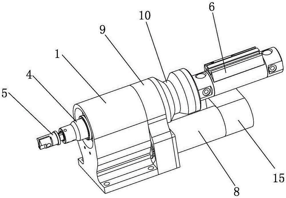
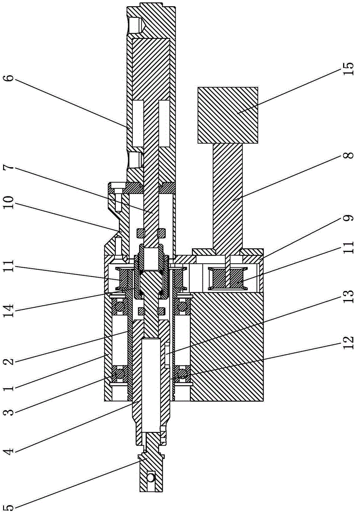
[0016] A V-shaped cutting angle device for cutting bed, comprising a fixed seat 1, a sleeve 2 is supported by a bearing 3 in the fixed seat 1, a connecting shaft 4 is sleeved in the sleeve 2, and the front end of the connecting shaft 4 is provided with The tool holder 5 and its rear end are connected to the output shaft 7 of the power device 6 fixed on the fixed seat 1. The power device 6 drives the connecting shaft 4 to move axially in the sleeve 2, and the servo motor 8 fixed on the fixed seat 1 The transmission mechanism drives the sleeve 2 to rotate, and the sleeve 2 drives the connecting shaft 4 to rotate. When in use, the device is installed on the cutting head of the cutting bed.

[0017] The rear end of the above-mentioned fixed base 1 is connected with a motor fixed cover 9, the servo motor 8 is fixed on the motor fixed c...


PUM


Abstract

The invention belongs to the technical field of cutting machine tool corner cutting and particularly relates to a V-shaped corner cutting device for a cutting machine tool. The V-shaped corner cutting device comprises a fixing seat. A sleeve is supported in the fixing seat through a bearing. A connecting shaft is sleeved with the sleeve. A cutter chuck is arranged at the front end of the connecting shaft and the rear end of the connecting shaft is connected with an output shaft of a power device fixed to the fixing seat. The power device drives the connecting shaft to move in the sleeve in the axial direction. A servo motor fixed to the fixing seat drives the sleeve to rotate through a transmission mechanism. The sleeve drives the connecting shaft to rotate. The V-shaped corner cutting device has the beneficial effects that when used, the V-shaped corner cutting device is installed on a cutting bit of the cutting machine tool, a V-shaped cutter is installed on the cutter chuck, the angle of the V-shaped cutter is adjusted through the servo motor in the use process, after the V-shaped cutter is orientated, an air cylinder drives the V-shaped cutter to move up and down so that a V-shaped cut notch can be cut on fabric, V-shaped cut notches in different directions can be cut by adjusting the V-shaped cutter through the servo motor at different angles, the cutting speed is high, and efficiency and accuracy are high.

Description

technical field [0001] The invention belongs to the technical field of cutting corners of cutting beds, in particular to a V-shaped corner cutting device for cutting beds. Background technique [0002] At present, traditional cutting machines generally use straight knives to realize the cutting of some single-layer flexible sheet materials such as leather for V-shaped notches. Generally, it is necessary to decelerate when cutting corners, which leads to frequent switching between acceleration and deceleration of straight tools, and in order to ensure that the cutting shape is V-shaped, it is necessary to lift the knife at the corner, so that when cutting "V" shape Two cuts have been carried out when cutting the V-shaped notch, so when the cutting machine cuts the V-shaped notch in the traditional way, the structure of the cutting device is complicated, the movement of the straight cutter is complicated, the cutting speed is relatively slow, the cutting efficiency is low, and...

Claims


Application Information

Patent Timeline
Patent Type & Authority Applications(China)
IPC IPC(8): C14B5/00
CPCC14B5/00C14B2700/113
Inventor 邵剑杜能平周超
Owner BULLMER ELECTROMECHANICAL TECH
Why Eureka
Try Eureka