
Vertical force floating powder laying scraper device for metal additive manufacturing

A scraper device and metal additive technology are applied in the directions of additive manufacturing, additive processing, and process efficiency improvement, which can solve the problems of reducing the surface quality of molded products and increasing surface defects, and achieve the effect of simple structure and stable process.

Active Publication Date: 2016-03-16
BEIJING E PLUS 3D TECH CO LTD
View PDF15 Cites 10 Cited by
  • Summary
  • Abstract
  • Description
  • Claims
  • Application Information

AI Technical Summary

Problems solved by technology

[0006] In the technical solution of Comparative Document 1, the avoidance of bumps is to make the powder spreading scraper pass through the bumps smoothly by moving the scraper up and down. However, when the scraper falls through the bumps, the scraper will produce a downward take-off process. , this process directly impacts the powder bed when it touches the metal powder behind the bump, which will cause a vibration pattern on the surface of the powder bed. After laser sintering, this vibration pattern will reduce the surface quality of the molded product, that is, increase the surface quality. defect

Method used


Image

  • Vertical force floating powder laying scraper device for metal additive manufacturing
  • Vertical force floating powder laying scraper device for metal additive manufacturing
  • Vertical force floating powder laying scraper device for metal additive manufacturing

Examples


Embodiment Construction

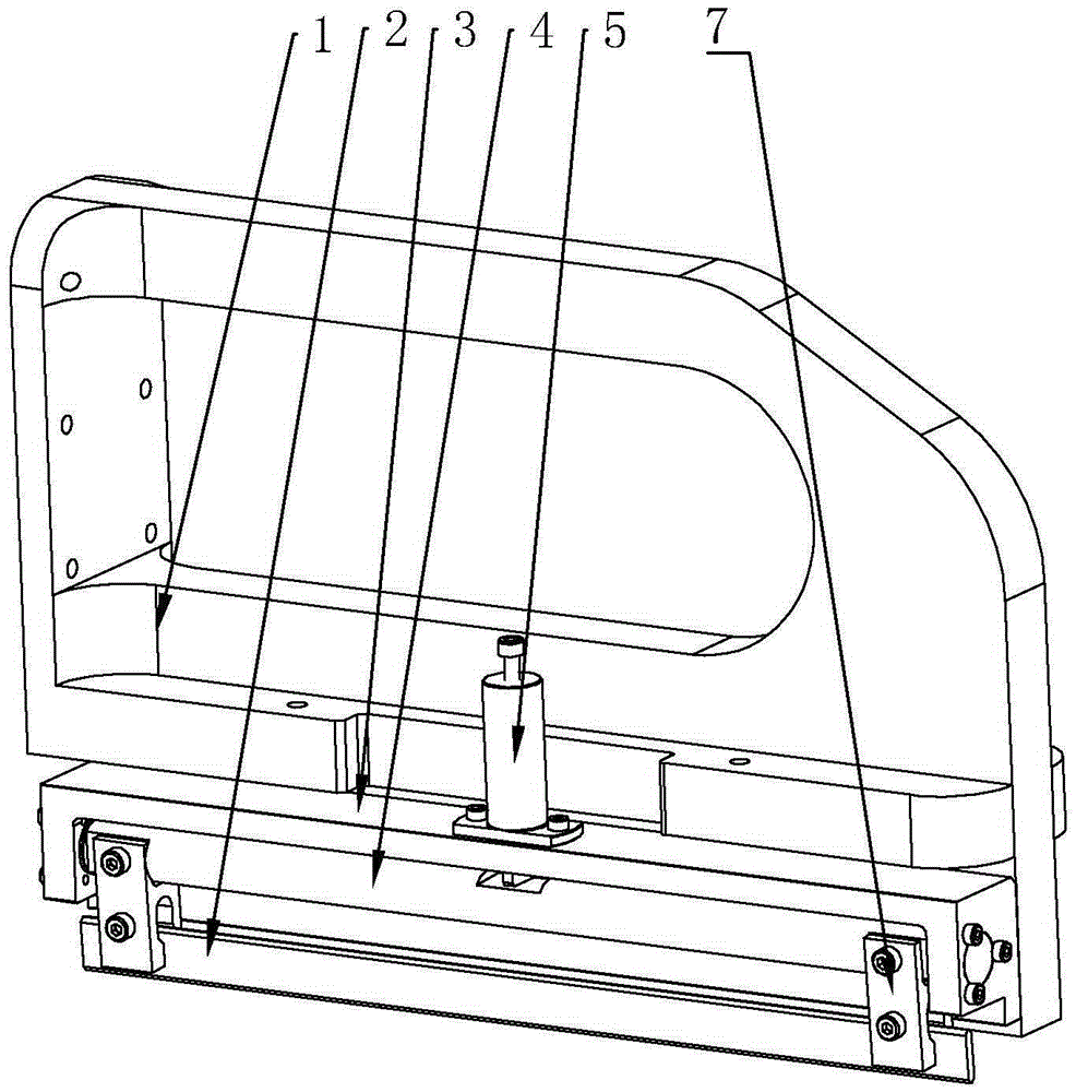
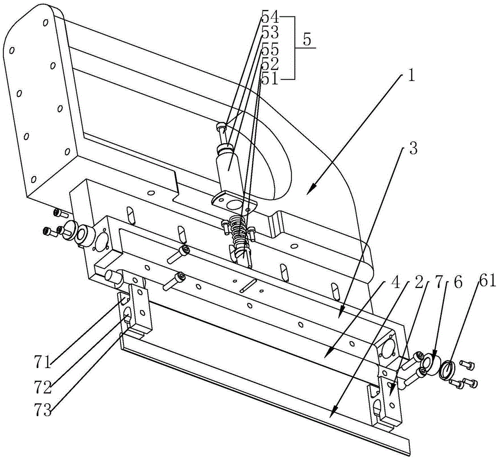
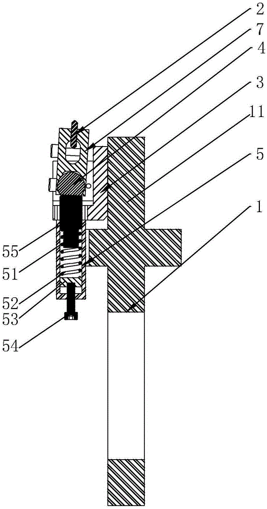
[0035] refer to Figure 1 to Figure 7 And embodiment the present invention is described further.

[0036] A vertical force floating powder spreading scraper device for metal additive manufacturing, such as figure 1 The three-dimensional structural view shown in includes a scraper bracket 1, a scraper 2 and a floating knife holder 3, wherein the scraper bracket 1 is externally connected with a power source that drives it to spread powder along a predetermined track on the powder bed, and the floating knife holder 3 is fixedly connected On the lower end face of the scraper support 1, a scraper 2 is fixedly connected at its lower end.

[0037] Specifically, as figure 2 As shown in the exploded view, the lower end of the scraper bracket 1 is provided with a mounting plate 11 along the extending direction of the scraper 2, and one end surface of the floating knife rest 3 is mounted on the mounting plate 11 and fixed to each other. There are a pair of supporting rotary holes 31 ...


PUM


Abstract

The invention discloses a vertical force floating powder laying scraper device. The technical problems in the process that a scraper avoids nodulizing protruding points of defects on a selective laser sintering surface in the prior art are solved. According to the technical scheme, the vertical force floating powder laying scraper device is characterized by comprising a scraper support externally connected with a drive source and a scraper connected between the scraper support and a powder bed; the end, close to the scraper, of the scraper support is provided with a floating scraper frame; the scraper is rotationally connected to the floating scraper frame; and when the scraper meets sintering defect protruding points in the powder laying direction, the floating scraper frame drives the central axis of the upper end face of the scraper to swing to bypass the sintering defect protruding points, and the technical effects that the scraper rotates to avoid the protruding points on the powder bed, a movement member causing destructiveness to structural functions due to direction collisions, shearing and the like of the scraper and the sintering defect protruding points is avoided, the critical defects that powder laying is uneven, a powder laying bed is loosened, and defects are moved backwards and transferred in other scraper powder laying manners are overcome, the yield of products is greatly increased, the mechanism is simple, and occupied space is small are achieved.

Description

technical field [0001] The invention relates to a laser selective area melting molding device, more specifically, it relates to a powder spreading scraper device used in laser selective area sintering equipment. Background technique [0002] Metal additive manufacturing, also known as laser selective melting molding technology, is an emerging rapid manufacturing process. Its working principle is to use the existing CAD / CAM software to design the path of the laser beam and fill it with an inert protective gas. The metal powder is laid layer by layer in the airtight molding chamber, and the laser beam is controlled to scan the metal powder distributed in layers according to the designed path to obtain the single-layer shape of the molded part; then, the molding cylinder is controlled to drop a layer thick distance, and the powder spreading device is restarted. Spread the powder and repeat the above molding process, so that the metal parts with specific geometric shapes are fin...

Claims


Application Information

Patent Timeline
Patent Type & Authority Applications(China)
IPC IPC(8): B22F3/105B33Y30/00
CPCB22F10/00B22F12/67B22F10/28Y02P10/25
Inventor 王志国马凤
Owner BEIJING E PLUS 3D TECH CO LTD
Learn More