
Unified-winding bearingless motor and drive control system thereof

A bearingless motor, drive control technology, applied in control systems, vector control systems, motor generator control and other directions, can solve problems such as increasing the hardware complexity of the control system, reducing the number of motor winding turns, and bridge arm straight-through, etc. The effect of making, avoiding straight-through, and simple winding structure

Active Publication Date: 2016-03-09
HUAZHONG UNIV OF SCI & TECH
View PDF5 Cites 12 Cited by
  • Summary
  • Abstract
  • Description
  • Claims
  • Application Information

AI Technical Summary

Problems solved by technology

At present, the main bearingless motors use two sets of windings for rotation and suspension and an independent drive control system. Compared with traditional inverter-driven motors, the hardware complexity of the control system is increased due to the use of two sets of systems. At the same time, due to the stator slot The addition of two sets of windings also reduces the number of turns of the motor windings, while the current new single-winding multi-phase magnetic suspension bearing uses the same winding, and the levitation force and rotation force are synthesized through the principle of current superposition, which improves the integration of the system. Each independent winding of the motor with this structure needs an independent H-bridge drive, and there is a risk of bridge arm through-through

Method used


Image

  • Unified-winding bearingless motor and drive control system thereof
  • Unified-winding bearingless motor and drive control system thereof
  • Unified-winding bearingless motor and drive control system thereof

Examples


Embodiment Construction

[0018] In order to make the object, technical solution and advantages of the present invention clearer, the present invention will be further described in detail below in conjunction with the accompanying drawings and embodiments. It should be understood that the specific embodiments described here are only used to explain the present invention, not to limit the present invention. In addition, the technical features involved in the various embodiments of the present invention described below can be combined with each other as long as they do not constitute a conflict with each other.

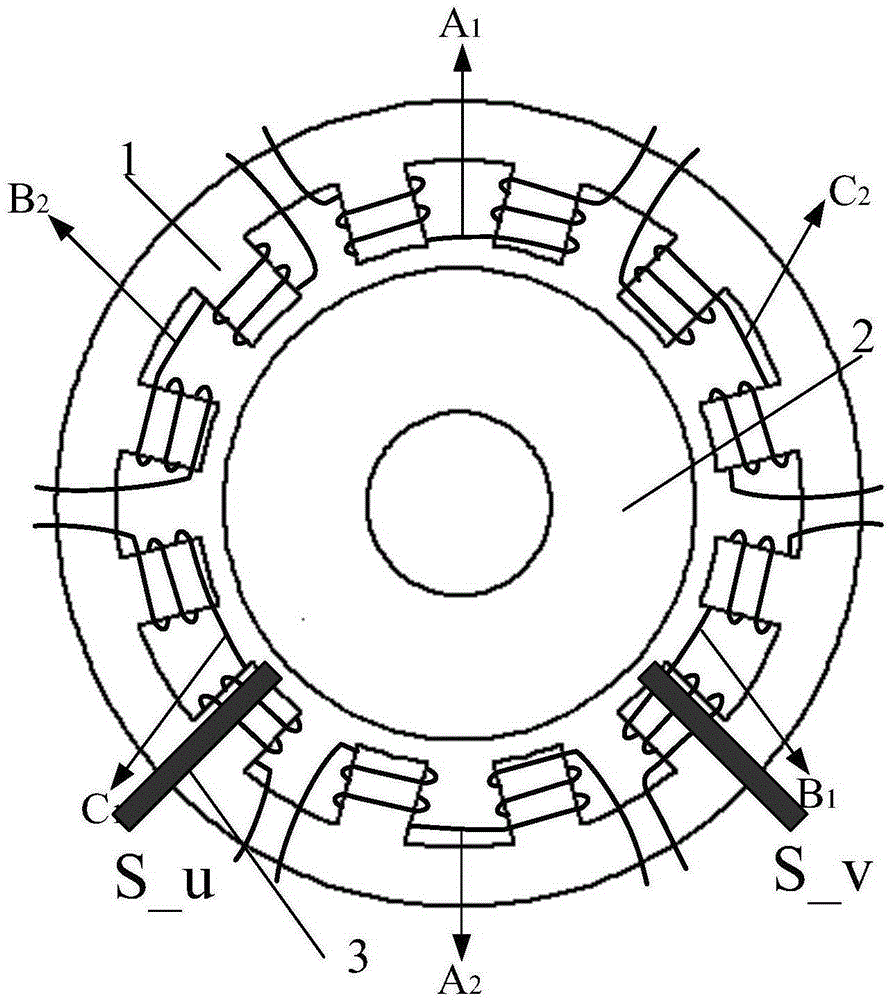
[0019] In this embodiment, firstly, a bearingless motor with unified winding is provided. The bearingless motor body with unified winding includes a stator 1, a rotor 2, and two displacement sensors 3 with a difference of 90 degrees for measuring the axial position of the rotor offset. Displacement sensor 3 according to as figure 1 The position shown can be used to obtain the displacement of th...


PUM


Abstract

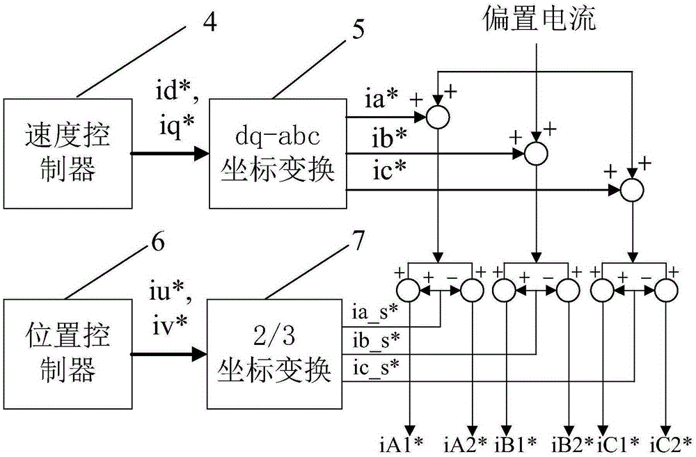
The invention discloses a unified-winding bearingless motor. The motor is characterized in that the motor comprises a stator and a rotor. Each two adjacent teeth arranged on the stator forms one pair; and for the two pair of opposite teeth arranged on the periphery of the stator based on a phase difference of 180 degree for each phase, one group of windings is arranged on one pair of teeth; and two sets of windings of each phase are driven by a drive module. Besides, two position sensors for measuring a deviation position of a rotor are arranged on the stator; and a 90-degree phase difference exists between the two position sensors. In addition, the motor also includes a drive control system connected with the drive module. According to the invention, the structure is simple; the rotor is suspended; no mechanical wearing phenomenon occurs; no mechanical bearing supporting is required; the hardware structure is simple; and a bridge shoot-through problem can be solved.

Description

technical field [0001] The invention belongs to the field of motors and their controls, and more specifically relates to a bearingless motor with unified windings and its drive control system. Background technique [0002] With the development of power electronics and control technology, new bearingless motors have been developed and applied in recent years to get rid of the dependence on traditional mechanical bearings. At present, the main bearingless motors use two sets of windings for rotation and suspension and an independent drive control system. Compared with traditional inverter-driven motors, the hardware complexity of the control system is increased due to the use of two sets of systems. At the same time, due to the stator slot The addition of two sets of windings also reduces the number of turns of the motor windings, while the current new single-winding multi-phase magnetic suspension bearing uses the same winding, and the levitation force and rotation force are ...

Claims


Application Information

Patent Timeline
Patent Type & Authority Applications(China)
IPC IPC(8): H02K3/28H02K11/21H02P21/22H02P25/02
CPCH02K3/28H02P25/02
Inventor 蒋栋曲荣海李大伟
Owner HUAZHONG UNIV OF SCI & TECH
Learn More