
Negative ion emission needle row assembly

A technology of negative ion emission and needle emission, which is applied in the direction of electrical components, etc., can solve the problems of increasing user burden, increasing use cost, and inability to replace separately, and achieves the effects of eliminating mutual pollution links, high production efficiency, and simple structure

Active Publication Date: 2016-03-09
盐城瑞龙电子科技有限公司
View PDF3 Cites 0 Cited by
  • Summary
  • Abstract
  • Description
  • Claims
  • Application Information

AI Technical Summary

Problems solved by technology

In addition, the components of the existing emitter pin structure usually fix multiple emitter pins together by injection molding, and multiple emitter pins are welded or integrally formed on the busbar. Although it is convenient to use, when one emitter fails, it cannot be used. To be replaced individually, the entire row needs to be replaced, which increases the user's burden, increases the cost of use, and the replacement efficiency is low

Method used


Image

  • Negative ion emission needle row assembly
  • Negative ion emission needle row assembly
  • Negative ion emission needle row assembly

Examples


Embodiment Construction

[0016] The present invention will be further described below in conjunction with the accompanying drawings, but the present invention is not limited to the scope of the described embodiments.

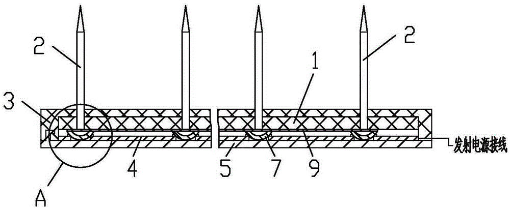
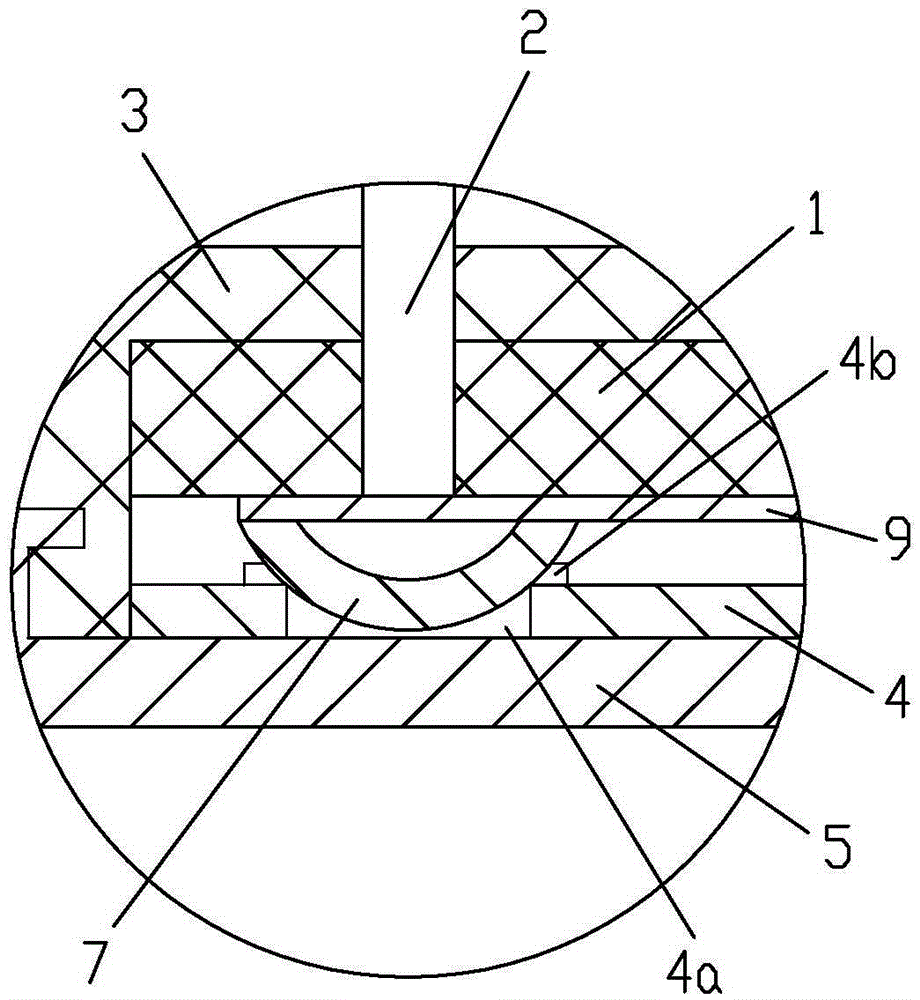
[0017] see figure 1 , figure 2 , image 3 , a negative ion emission needle row assembly, comprising a combination of a plurality of emission needles 2 through a base plate 1 to form an emission pin set, the base plate 1 is in the structure of a printed circuit board, the base plate 1 is arranged in the bottom box 3, and one side of the base plate 1 abuts against the bottom At the bottom of the box 3, the launch pins 2 extend out of the bottom box 3 through the pinholes of the bottom box 3, and the other side of the substrate 1 is provided with a busbar 4, and the busbar 4 is pressed and fixed by the box cover 5 so that it is connected to a plurality of launch pins 2 Both form an electrical connection; the passing tail of the emitting pin 2 is riveted and fixed with the substrate 1 . ...


PUM


Abstract

The invention discloses a negative ion emission needle row assembly. The negative ion emission needle row assembly comprises an emission needle row which is formed by combination of a plurality of emission needles and a substrate; the substrate is a printed circuit board structure and arranged in a bottom box; one side of the substrate is in abutting joint with the bottom of the bottom box; the emission needles extend out of the bottom box through needle holes of the bottom box; a motherboard is arranged at the other side of the substrate; the motherboard is fixed through top pressure of a box cover, such that the motherboard is electrically connected with the plurality of emission needles; the emission needles are riveted and fixed with the substrate through tail parts; preferably, the tail parts of the emission needles are arc roof structured tin soldering stacks formed by surfacing of soldering tin; the motherboard is in abutting joint with the tail parts of the emission needles through support holes; and a tin soldering stack welding ring formed by surfacing of soldering tin is formed on the periphery of the orifice of the support hole at the riveting head side of the tail part of the emission needle. The negative ion emission needle row assembly disclosed by the invention has the benefits that: the emission needles at the emission end are convenient to replace and reliable in electric connection; the negative ion emission needle row assembly is simple in structure, convenient to assemble and disassemble and high in production efficiency and reliability; and single emission needle can also be washed or cleaned.

Description

technical field [0001] The patent of the present invention relates to an anion emitting end component, in particular to an anion emitting needle row assembly. Background technique [0002] Negative ion air purifier is an environment-optimized appliance that uses its own negative ions to purify, remove dust, deodorize, and sterilize the air. Harmful substances in the air, while traditional air purifiers use a fan to draw air and use a filter to filter dust to purify the air. This is called the passive adsorption filter purification principle, and the filter needs to be replaced regularly, while the negative ion air purifier does not need consumables. The emitting end of the negative ion purifier includes multiple rows of emitting head assemblies, and each assembly is provided with a plurality of emitting heads. The emitter head mainly has two structural forms: emitter needle and carbon fiber bundle. The carbon fiber bundle is connected to the terminal through the metal head,...

Claims


Application Information

Patent Timeline
Patent Type & Authority Applications(China)
IPC IPC(8): H01T23/00
CPCH01T23/00
Inventor 赵平
Owner 盐城瑞龙电子科技有限公司
Learn More