Flow-type fluorescence detector

A flow fluorescence and detector technology, which is applied in the direction of fluorescence/phosphorescence, instruments, measuring devices, etc., can solve the problems of unstable optical detection, inaccurate detection results, and unstable structure, etc., and achieve stable optical detection performance and detection Effects with a wide range and simple structure

Active Publication Date: 2016-03-09
JIAXING QUEST LIFE SCI
View PDF5 Cites 1 Cited by
  • Summary
  • Abstract
  • Description
  • Claims
  • Application Information

AI Technical Summary

Problems solved by technology

[0004] The existing flow fluorescence detectors on the market are not very stable in structure, resulting in unstable optical detection, and the detection results are not accurate enough. Therefore, they have certain limitations.

Method used


Image

  • Flow-type fluorescence detector
  • Flow-type fluorescence detector
  • Flow-type fluorescence detector

Examples


Embodiment Construction

[0050] Below in conjunction with accompanying drawing and embodiment the present invention is described in further detail:

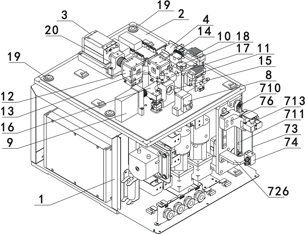
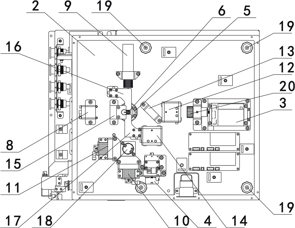
[0051] As an embodiment of the flow type fluorescence detector of the present invention, such as figure 1 and figure 2 As shown, it is used to draw and detect the sample in the cuvette (not shown in the figure), and the flow fluorescence detector includes a frame body 1, an optical platform 2, a first laser 3, a second laser 4, and a flow chamber 5. A flow cell 6, four light receivers and a sample suction device 7, the first laser 3, the second laser 4, the flow chamber 5, the flow cell 6 and the four light receivers are all arranged on the optical platform 2, The flow chamber 5 is located below the flow cell 6, the light generated by the first laser 3 and the second laser 4 is received by four light receivers through the flow cell 6, and the sample suction device 7 is vertically arranged on the frame body 1 on and above the cuvette.

[0052] like ...


PUM


Abstract

The invention relates to the technical field of medical equipment, in particular to a flow-type fluorescence detector. The flow-type fluorescence detector is used for sucking samples in a reaction cup for detection. The flow-type fluorescence detector is characterized in that the detector comprises a frame body, an optical table, a first laser device, a second laser device, a flow chamber, a flow pond, a plurality of optical receivers and a sample sucking device; the first laser device, the second laser device, the flow chamber, the flow pond and the optical receivers are all arranged on the optical table; the flow chamber is located below the flow pond; light generated by the first laser device and the second laser device passes through the flow pond to be received by the optical receivers; the sample sucking device is vertically arranged on the frame body and located above the reaction cup. The flow-type fluorescence detector is simple and stable in structure, high in detection sensitivity, wide in detection range and stable in optical detection.

Description

technical field [0001] The invention relates to the technical field of medical equipment, in particular to a flow type fluorescence detector. Background technique [0002] Flow fluorescence detector, with fluorescent coded microspheres as the core, is a multi-indicator parallel analysis technology platform integrating flow principle, laser analysis, high-speed digital signal processing and other technologies, which can accurately and quantitatively detect 100 different Biomolecules; with the characteristics of high throughput, high sensitivity, parallel detection, etc.; can be used in various aspects and fields of research such as immunoassay, nucleic acid research, enzymatic analysis, receptor, ligand recognition analysis, etc. [0003] The technical principle of flow cytometry is as follows: the fluorescently labeled single cell (or particle) suspension enters the aspirator, and then enters the flow chamber with the sheath fluid. The pipe before entering the flow chamber ...

Claims


Application Information

Patent Timeline
IPC IPC(8): G01N21/64
CPCG01N21/6402
Inventor 黄鹤刘和何姜润涛张海峰
Owner JIAXING QUEST LIFE SCI
Why Eureka
Try Eureka