circuit breaker

A circuit breaker and circuit technology, applied in the direction of electromagnetic release switch, protection switch operation/release mechanism, etc., can solve the problems of increasing the tripping load of the abutment plate, difficult operation, unstable tripping action, etc., and achieve the effect of reducing the tripping load

Active Publication Date: 2017-10-13
MITSUBISHI ELECTRIC CORP
View PDF1 Cites 0 Cited by
  • Summary
  • Abstract
  • Description
  • Claims
  • Application Information

AI Technical Summary

Problems solved by technology

That is, the torsion spring that applies a moment to the abutment plate of the latch plate continues to apply a moment to the abutment plate even in the ON state, so there is a problem of increasing the trip load of the abutment plate. In addition, if the trip load increases, Then, the miniaturization of the trip device that trips the abutment plate will be hindered, and there is no margin for the trip force of the trip device, and there is a problem that the operation of the trip becomes unstable.
[0005] In addition, in order to be suitable for automatic assembly, a structure that can be easily assembled is generally required. However, the frame of the above-mentioned mechanism is a structure that combines two metal plates that have been bent. The torsion spring is formed inside the metal plate. If you want to hook the foot of the spring after combining the frame, it is located in the deepest part, so the work becomes difficult. Depending on the situation, it is necessary to move the robot with precision. equipment becomes expensive
In addition, if the above-mentioned spring is located outside the frame, the hooking of the spring can be facilitated, but it is necessary to prevent the spring from coming off.

Method used


Image

  • circuit breaker
  • circuit breaker
  • circuit breaker

Examples


Embodiment approach 1

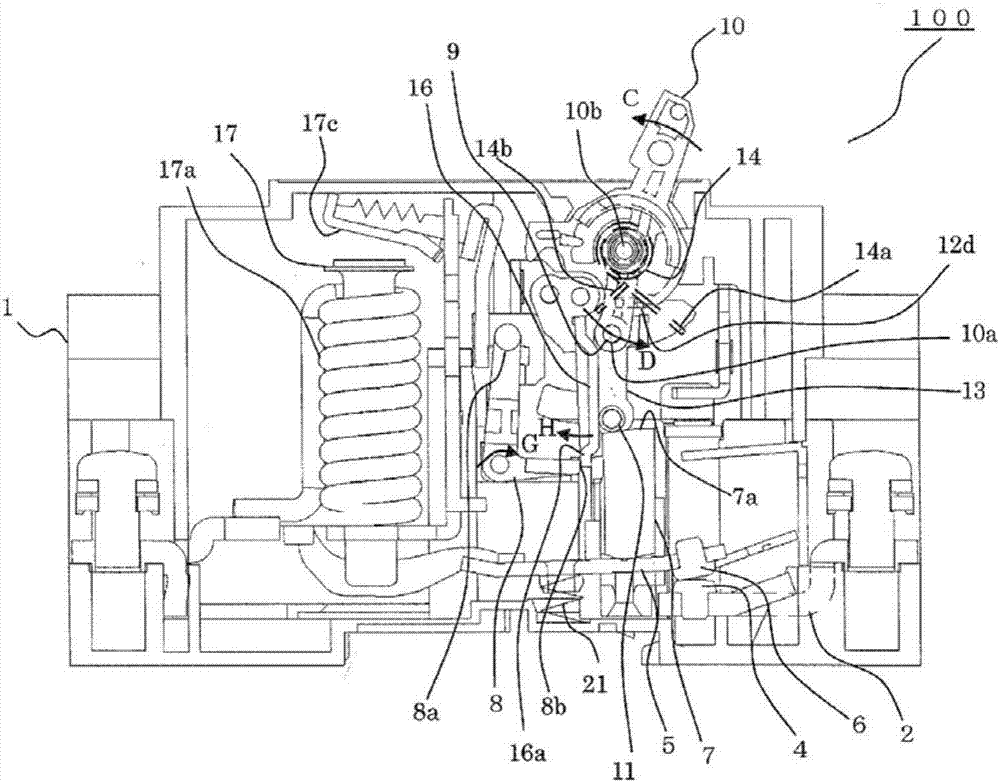
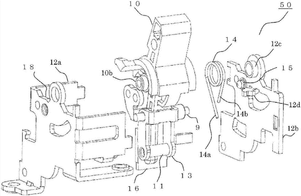
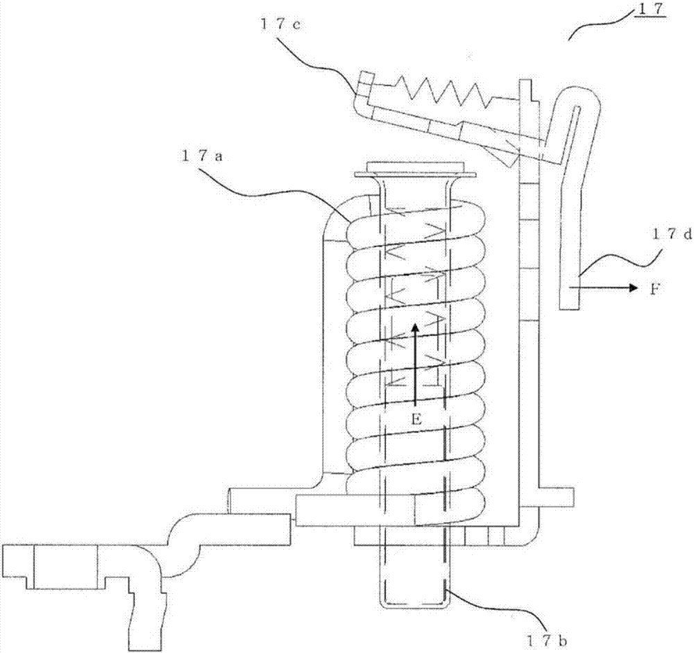
[0021] Figure 1 ~ Figure 7 Is a diagram showing a circuit breaker in Embodiment 1 of the present invention, in figure 1 , figure 2 In this case, the circuit breaker 100 is composed of a housing 1 made of an insulating material, and the following components respectively contained in the housing 1, and other components. That is, the components respectively contained in the housing 1 are: The externally operated manual handle 10; the fixed contact conductor 2 provided with the fixed contact 4; the movable contact conductor 5 provided with the movable contact 6 contacting / separating from the fixed contact 4; and the above-mentioned fixed contact 4 The opening / closing mechanism part 50 for making and breaking operations with the movable contact 6.

[0022] The opening and closing mechanism section 50 has: a pressing plate 7, which is made of an insulating material, and extends along the not-shown groove of the frame 1 while maintaining the engagement with the movable contact conduct...


PUM


Abstract

The present invention provides a circuit breaker that does not require additional components, is compatible with automatic assembly, and realizes miniaturization and stable operation. The circuit breaker of the present invention is characterized in that it has: a pressure plate that moves the movable contact conductor to engage the movable contact with the fixed contact; On and off operation to engage with the pressure plate, overcome the pressure of the separation spring, press the pressure plate down, and lift the pressure plate by the pressure of the separation spring through the release of the trip lever; disconnecting the trip spring, which is a torsion spring having a long foot and a short foot, and held at a spring locking shaft corresponding to the rotation shaft of the manual handle; and an engaging protrusion, which is provided on the Just below the spring locking shaft, lock the long leg and short leg of the off trip spring in a state of intersecting each other, and the long leg is set to engage with the link pin inserted through the manual handle. The length of the short foot is set to a length that does not engage with the above-mentioned link pin.

Description

Technical field [0001] The present invention relates to circuit breakers such as circuit breakers for wiring and earth leakage circuit breakers, and more particularly to the trip mechanism of the circuit breaker. Background technique [0002] In a circuit breaker with a known quick-connection mechanism that quickly connects the contacts regardless of the operating speed of the manual handle, the main spring ensures the tripping force of the lever, which can be independent of the on and off states of the mechanism The tripping force, that is, the auxiliary switching force, is ensured, but the circuit breaker with the slow-connection mechanism does not have the above-mentioned main spring. Instead of the main spring, the structure to obtain the tripping force of the lever is constructed by the lifting force of the pressure plate. In the disconnected state, the pressure plate is locked by the stopper. Therefore, in the disconnected state, the tripping force cannot be guaranteed and ...

Claims


Application Information

Patent Timeline
Patent Type & Authority Patents(China)
IPC IPC(8): H01H73/36H01H71/24
CPCH01H71/24H01H71/52H01H73/36H01H73/38
Inventor 千种真一三好伸郎
Owner MITSUBISHI ELECTRIC CORP
Why Eureka
Try Eureka