
Projection display system and correction method of projection area

A projection area and projection display technology, which is applied in the field of projection systems, can solve problems such as deformation of the imaging screen and reduce the projection quality of the imaging screen, and achieve the effect of improving the projection quality

Inactive Publication Date: 2016-03-02
CORETRONIC
View PDF25 Cites 28 Cited by
  • Summary
  • Abstract
  • Description
  • Claims
  • Application Information

AI Technical Summary

Problems solved by technology

[0003] However, the spliced ​​imaged image may be distorted because the projection surface projected by the projector is not flat (for example, the projector projects to a curved, wavy or irregularly shaped projection screen); another On the one hand, when multiple projectors are splicing images, the overlapping range of the projection area may exceed the preset size, which may cause unavoidable bright bands in the imaged image, thereby reducing the projection quality of the imaged image

Method used


Image

  • Projection display system and correction method of projection area
  • Projection display system and correction method of projection area
  • Projection display system and correction method of projection area

Examples


Embodiment Construction

[0032] The foregoing and other technical contents, features and effects of the present invention will be clearly presented in the following detailed description of multiple embodiments with reference to the accompanying drawings. The directional terms mentioned in the following embodiments, such as "upper", "lower", "front", "rear", "left", "right", etc., are only referring to the directions of the drawings. Accordingly, the directional terms are used to illustrate, not to limit, the invention.

[0033] In order to maintain the projection quality of the image frame spliced ​​by multiple projection areas, an embodiment of the present invention provides a projection display system. The projection display system can set the control point of the projection area on the control interface provided or mark the boundaries of the overlapping parts of each projection area. Therefore, the user can dynamically adjust the projection ratio and overlapping effect of the imaging image through...


PUM


Abstract

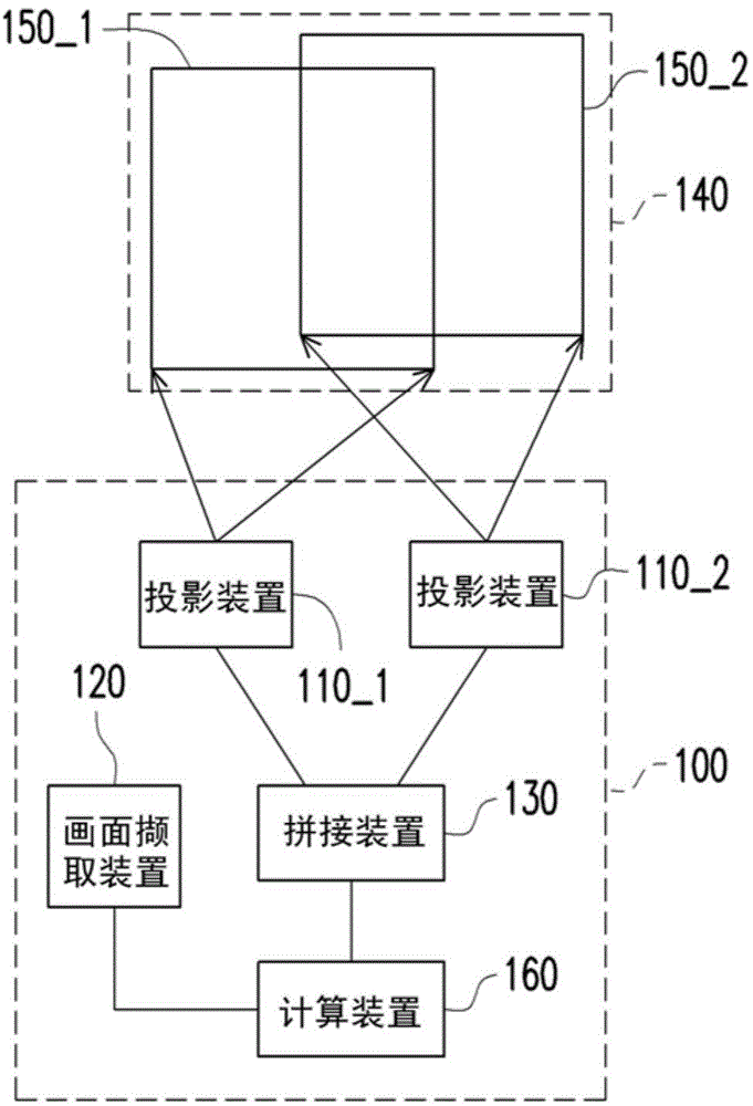
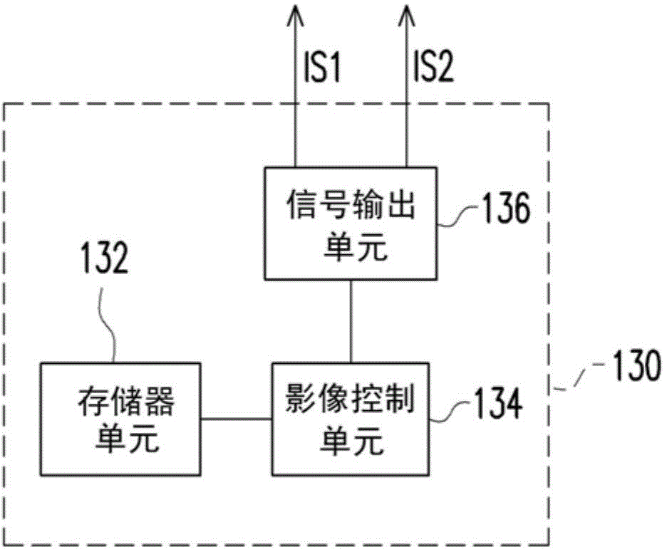
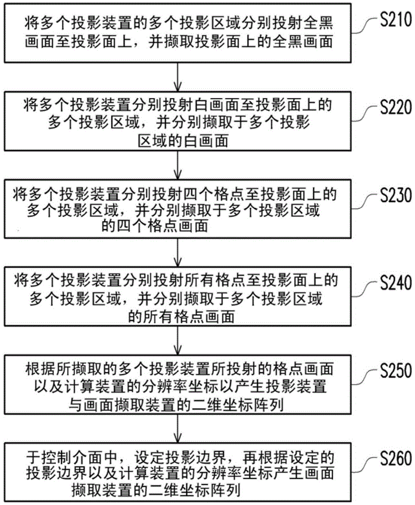
The invention provides a projection display system and a correction method of a projection area. A projection display device comprises a multiple protection devices, an image capturing device, a splicing device and a computing device. The projection devices are used for projecting multiple projection areas in a projection plane. The image capturing device is used for capturing the imaging image on the projection plane. The coumputing device judges the positions of the projection areas through the imaging image captured by the image capturing device. The display screen of the computing device is used for displaying a control interface which is corresponding to the display image area of the projection areas according to a ratio. The computing device dynamically adjusts the projection ratio of the images displayed in the projection areas through adjusting the positions of the control points in the display image area and the distance between control points.

Description

technical field [0001] The invention relates to a projection system, and in particular to a projection display system with multiple projection devices and a correction method for projection areas. Background technique [0002] Due to the considerable difficulty in manufacturing large-scale displays, when it is necessary to share a large-scale image to the audience to meet the sound and light effects, multiple projection devices and master control machines can be used to splice the images so as to fully integrate the content to be shared. projection. Therefore, a broader screen effect can be displayed, and the brightness and color performance of the projection screen can be increased by increasing the number of projection devices. The user can also manually adjust the required imaging picture and effect through the software or control interface provided by the main control machine. Related patents on screen splicing technology through multiple projectors include US Patent P...

Claims


Application Information

Patent Timeline
IPC IPC(8): H04N9/31H04N5/74G03B21/56
Inventor 林玮伦陈睿骐钱俊霖
Owner CORETRONIC
Learn More