Laser device based on self-raman and OPO combination

A combination of lasers and lasers, applied in the field of lasers, can solve the problems of high cost, difficult adjustment, complex laser cavity structure, etc., and achieve the effect of compact structure and convenient adjustment

Inactive Publication Date: 2016-03-02
CHINA UNIV OF PETROLEUM (EAST CHINA)
View PDF4 Cites 2 Cited by
  • Summary
  • Abstract
  • Description
  • Claims
  • Application Information

AI Technical Summary

Problems solved by technology

The structure of the entire laser cavity is relatively complex, the cost is relatively high, and the adjustment is difficult

Method used


Image

  • Laser device based on self-raman and OPO combination
  • Laser device based on self-raman and OPO combination
  • Laser device based on self-raman and OPO combination

Examples


Embodiment 1

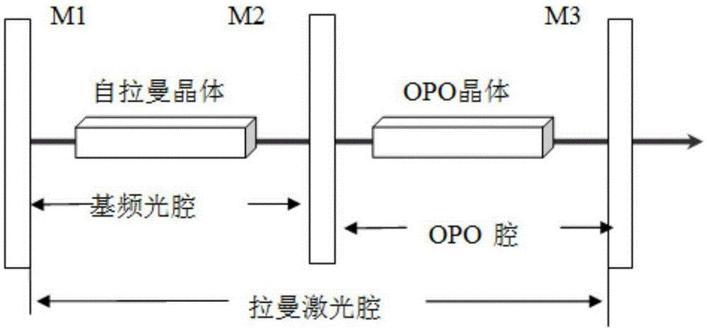
[0049] Such as figure 1 As shown, cavity mirror M1 and cavity mirror M2 form a fundamental frequency optical cavity, M2 and cavity mirror M3 form an OPO cavity, M1 and M3 form a Raman optical cavity,

[0050] The fundamental frequency optical cavity is isolated from the OPO optical cavity, and the Raman optical cavity covers the fundamental frequency optical cavity and the OPO optical cavity.

[0051] Coating requirements are as follows: M1 is highly reflective to fundamental frequency light and Raman light; one side of M2 is to fundamental frequency light, and the other is highly reflective to parametric light (signal light and (or) idler light). High transmittance of Raman light; M3 is highly reflective to Raman light and partially transmits to parametric light (signal light and (or) idler light);

[0052] Self-Raman crystal coating enhances the transmission of fundamental frequency light and Raman light;

[0053] OPO crystal coating is anti-reflective to Raman light and p...

Embodiment 2

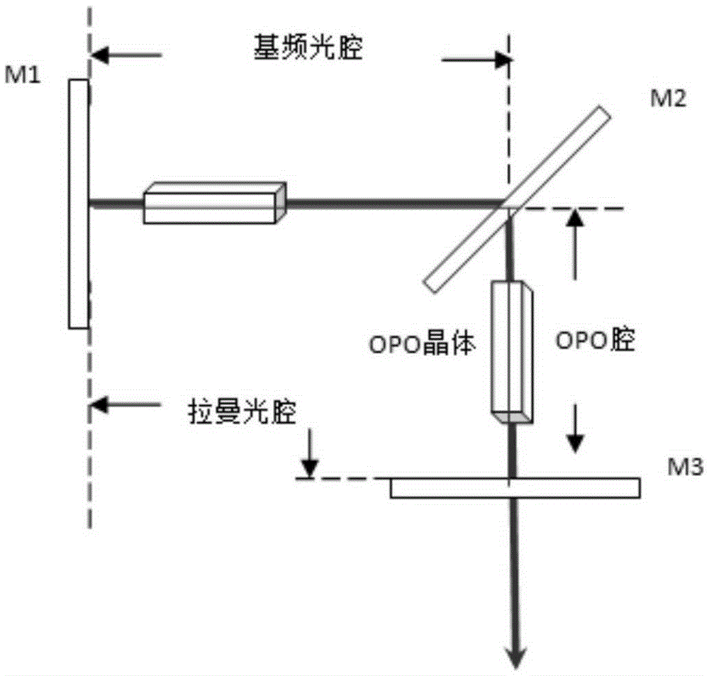
[0057] Such as figure 2 As shown, the line connecting the first cavity mirror and the second cavity mirror forms a right angle or other angles with the line connecting the second cavity mirror and the third cavity mirror, and other settings are consistent with the first embodiment.

Embodiment 3

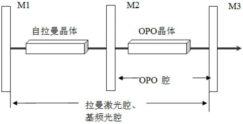
[0059] Such as image 3 As shown, M1 and M3 form a fundamental frequency optical cavity, which is also a Raman optical cavity, and M2 and M3 form an OPO cavity. The fundamental frequency light and the Raman optical cavity coincide.

[0060] Coating requirements: M1 is highly reflective to fundamental frequency light and Raman light; M2 is highly reflective to parametric light (signal light and (or) idler light) on one side, and highly transparent to Raman light and fundamental frequency light on both sides; M3 is highly reflective to parametric light (signal light and (or) idler light) Fundamental frequency light and Raman light are highly reflective, and partly transmitted to parametric light (signal light and (or) idler light);

[0061] Self-Raman crystal coating enhances the transmission of fundamental frequency light and Raman light;

[0062] OPO crystal coating is anti-reflective to fundamental frequency light, Raman light and parametric light (signal light and (or) idl...


PUM


Abstract

The invention discloses a laser device based on a self-raman and OPO combination. The laser device comprises a first cavity mirror, a second cavity mirror and a third cavity mirror, wherein a self-raman crystal is arranged between the first cavity mirror and the second cavity mirror; an OPO crystal is arranged between the second cavity mirror and the third cavity mirror; the first cavity mirror, the second cavity mirror and the third cavity mirror are coated, so that a fundamental optical cavity is formed between the first cavity mirror and the second cavity mirror; an OPO cavity is formed between the second cavity mirror and the third cavity mirror; a raman laser cavity is formed between the first cavity mirror and the third cavity mirror; the self-raman crystal finishes wavelength conversion from pump light to fundamental light and from the fundamental light to raman light; the raman light pumps the OPO crystal as a pumping source, and finishes the wavelength conversion from the raman light to OPO parametric light. A self-raman laser operation is achieved with a self-raman medium, and an OPO medium is pumped by the raman light as the pumping source, so as to finish optical parametric conversion; and meanwhile, a tunable laser with a long wavelength is generated by a tuning technology.

Description

technical field [0001] The invention relates to a laser based on the combination of self-Raman and OPO. Background technique [0002] Nonlinear optical frequency conversion technology is one of the important research contents and research hotspots in the field of optics at present. Its purpose is to seek coherent light of various wavelengths to meet the needs of practical applications. Stimulated Raman scattering (StimulatedRamanscattering, SRS) is an efficient nonlinear frequency conversion process, and is an effective way to realize laser frequency conversion. In recent years, with the development of crystal Raman material growth technology, solid-state Raman lasers based on the stimulated Raman scattering effect of crystals have attracted widespread attention due to their small size, high efficiency, and good stability. It has important applications in the fields of medical treatment, transportation, measurement and national defense, and has become a current research hot...

Claims


Application Information

Patent Timeline
Patent Type & Authority Applications(China)
IPC IPC(8): H01S3/30H01S3/16
CPCH01S3/163H01S3/30
Inventor 白芬徐先锋张会董鹏
Owner CHINA UNIV OF PETROLEUM (EAST CHINA)
Why Eureka
Try Eureka