
A manual energy storage device for a circuit breaker

A technology of energy storage device and circuit breaker, applied in the direction of protection switch operation/release mechanism, etc., can solve the problems of weak humanization, reduced operation force, inconvenient use, etc., to optimize structure, improve reliability, and reduce assembly. effect of difficulty

Active Publication Date: 2017-09-05
SHANGHAI LIANGXIN ELECTRICAL
View PDF6 Cites 0 Cited by
  • Summary
  • Abstract
  • Description
  • Claims
  • Application Information

AI Technical Summary

Problems solved by technology

[0005] The purpose of the present invention is to provide a manual energy storage device for a circuit breaker in view of the technical defects of the above-mentioned existing manual energy storage device, which are inconvenient to use, not strong in humanization, and complicated to assemble. It is changed to the rocker rotating energy storage, which reduces the operating force required for energy storage, reduces the difficulty of assembly at the same time, optimizes the structure of the product, and improves the reliability of the manual energy storage device of the circuit breaker

Method used


Image

  • A manual energy storage device for a circuit breaker
  • A manual energy storage device for a circuit breaker
  • A manual energy storage device for a circuit breaker

Examples


Embodiment 1

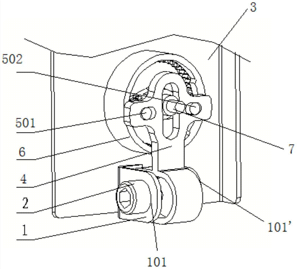
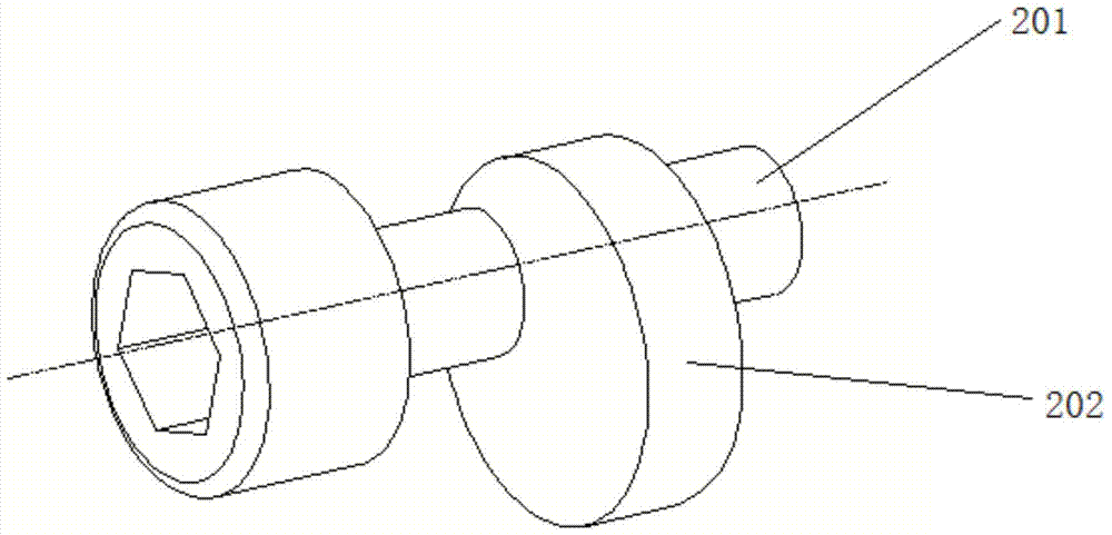
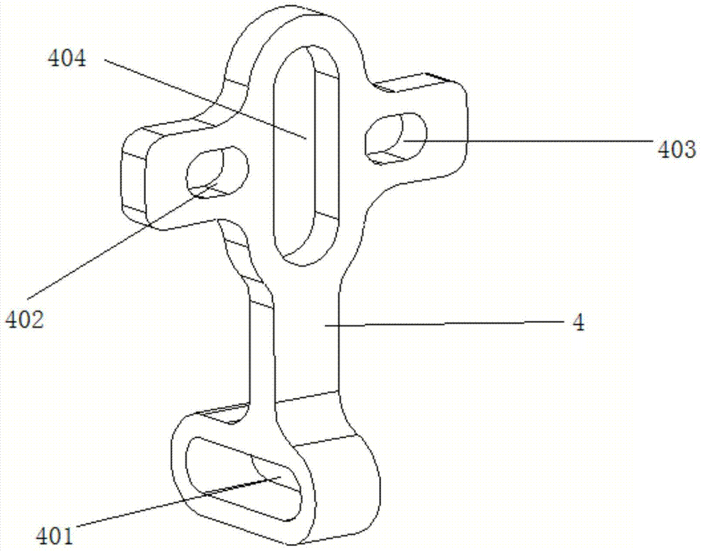
[0025] as attached Figure 1~5 As shown, a manual energy storage device for a circuit breaker is characterized in that it includes a fixed support frame 1, an eccentric rotation mechanism 2 is mounted on the fixed support frame 1, the eccentric rotation structure 2 is connected with a reciprocating connecting rod 4, and the eccentric rotation mechanism The rotation of 2 can drive the reciprocating connecting rod 4 to reciprocate back and forth. The reciprocating connecting rod 4 is connected with a swing lever mechanism group 5, and the swing lever mechanism group 5 is engaged with the ratchet 6. The reciprocating movement of the reciprocating connecting rod 4 can drive the swing lever The mechanism group 5 stirs the ratchet 6 to rotate, and the ratchet 6 is contained on the energy storage mechanism camshaft 7, and the rotation of the ratchet 6 can drive the energy storage mechanism camshaft 7 to rotate to realize energy storage.

[0026] The fixed support frame 1 is installed...

Embodiment 2

[0033] as attached Figure 6 As shown, the eccentric rotation mechanism 2 can also be a crankshaft mechanism, the two ends of the crankshaft of the crankshaft mechanism are installed in the two support holes 101, 101' of the fixed support frame 1, and the crankshaft center of the crankshaft is installed at the lower end of the reciprocating connecting rod 4 In the lower oblong hole 401 of the lower oblong hole.

Embodiment 3

[0035] The fixed support frame 1 can also be installed on the circuit breaker body.

[0036] The working principle of the present invention is to shake the handle to input torque to the eccentric rotation mechanism 2, the eccentric rotation mechanism 2 drags the reciprocating link 4 to perform reciprocating motion, and the reciprocating link 4 drags the left swing lever mechanism 501 and the right swing lever mechanism 502 to perform reciprocation Swing the left swing lever mechanism 501 and the right swing lever mechanism 502, and drive the ratchet wheel 6 to rotate through the engagement of the pawls with the ratchet wheel 6. Since the left swing lever mechanism 501 and the right swing lever mechanism 502 alternately drag the ratchet wheel 6 to rotate, so no matter Whether the reciprocating link 4 moves downward or upward, the ratchet 6 can drive the camshaft 7 of the energy storage mechanism to rotate and store energy; Moving the left swinging lever mechanism 501 and the ri...


PUM


Abstract

A manual energy storage device for a circuit breaker, which includes a fixed support frame (1), the fixed support frame (1) is equipped with an eccentric rotation mechanism (2), and the eccentric rotation structure (2) is connected with a reciprocating connecting rod (4), The rotation of the eccentric rotation mechanism (2) can drive the reciprocating connecting rod (4) to do back and forth reciprocating motion, and the reciprocating connecting rod (4) is connected with a swing lever mechanism group (5), and the swing lever mechanism group (5) and the ratchet ( 6) The engaging ratchet (6) is mounted on the energy storage mechanism camshaft (7), and the rotation of the ratchet (6) can drive the energy storage mechanism camshaft (7) to rotate to realize energy storage. The present invention changes the traditional one-way rotational energy storage into that when the handle is operated for energy storage, no matter the handle is shaken clockwise or counterclockwise, the mechanism can store energy, making the energy storage operation more efficient and easier to operate. The operation force is smaller, which is more in line with the comfort of the human body when performing energy storage operations, and at the same time reduces the difficulty of assembly, optimizes the structure of the product, and improves the reliability of the manual energy storage device of the circuit breaker.

Description

technical field [0001] The invention belongs to the technical field of low-voltage electrical equipment, and in particular relates to a manual energy storage device for a circuit breaker. Background technique [0002] Circuit breakers are divided into high-voltage circuit breakers and low-voltage circuit breakers according to their scope of use. Low-voltage circuit breaker, also known as automatic switch, commonly known as "air switch", also refers to low-voltage circuit breaker. It is an electrical appliance that not only has the function of manual switch, but also can automatically protect against voltage loss, undervoltage, overload, and short circuit. It can be used to distribute electric energy, start asynchronous motors infrequently, protect power lines and motors, etc., and can automatically cut off the circuit when they have severe overload, short circuit and undervoltage faults. Its function is equivalent to a fuse switch and The combination of overheating and unde...

Claims


Application Information

Patent Timeline
Patent Type & Authority Patents(China)
IPC IPC(8): H01H71/10
Inventor 贾超举李建荣付春秋任山波何贵波
Owner SHANGHAI LIANGXIN ELECTRICAL
Learn More