Gas tight test board of hydraulic valve
A technology for air tightness testing and hydraulic valves, which is applied in fluid tightness testing, liquid tightness measurement using liquid/vacuum degree, machine/structural component testing, etc. It can solve the problems of low detection efficiency, air pressure and air leakage Insufficient inspection accuracy and other issues, to achieve high explosion-proof safety performance, compact structure, and high work efficiency
- Summary
- Abstract
- Description
- Claims
- Application Information
AI Technical Summary
Problems solved by technology
Method used
Image
Examples
Embodiment 1
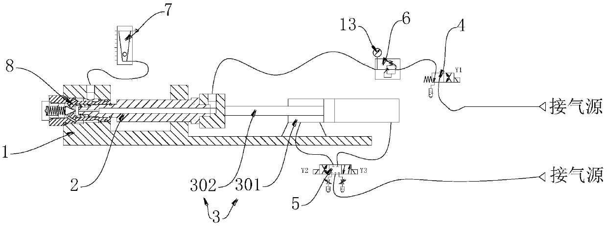
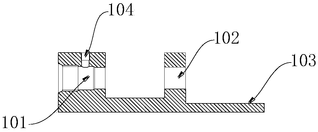
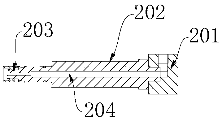
[0022] Embodiment 1 of the present invention: as Figures 1 to 3 As shown, a hydraulic valve airtight test bench includes a first station A, characterized in that the first station A includes a test unit A1 and an installation unit A2, and the test unit A1 includes a valve block component 1, Sealing tooling 2, pneumatic two-position four-way reversing valve 4, first pneumatic pressure reducing valve 6 and gas glass rotameter 7; said installation unit A2 includes cylinder 3 and pneumatic three-position five-way reversing valve 5; said The valve block part 1 includes a valve body installation part 101, a tooling installation part 102, a cylinder installation part 103 and a gas discharge port 104; the cylinder 3 includes a cylinder barrel 301 and a piston rod 302; the sealing tooling 2 includes a tooling exhaust part 203 , the tooling fixing part 202, the tooling air intake part 201 and the tooling internal through hole 204.
[0023] The cylinder barrel 301 of the cylinder 3 is ...
Embodiment 2
[0026] Embodiment 2 of the present invention: as Figure 4 As shown, a hydraulic valve airtight test bench includes a first station A, characterized in that the first station A includes a test unit A1 and an installation unit A2, and the test unit A1 includes a valve block component 1, Sealing tooling 2, pneumatic two-position four-way reversing valve 4, first pneumatic pressure reducing valve 6 and gas glass rotameter 7; said installation unit A2 includes cylinder 3 and pneumatic three-position five-way reversing valve 5; said The valve block part 1 includes a valve body installation part 101, a tooling installation part 102, a cylinder installation part 103 and a gas discharge port 104; the cylinder 3 includes a cylinder barrel 301 and a piston rod 302; the sealing tooling 2 includes a tooling exhaust part 203 , the tooling fixing part 202, the tooling air intake part 201 and the tooling internal through hole 204.
[0027] The cylinder barrel 301 of the cylinder 3 is fixedl...
Embodiment 3
[0031] Embodiment 3 of the present invention: as Figure 5 As shown, a hydraulic valve airtight test bench includes a first station A, characterized in that the first station A includes a test unit A1 and an installation unit A2, and the test unit A1 includes a valve block component 1, Sealing tooling 2, pneumatic two-position four-way reversing valve 4, first pneumatic pressure reducing valve 6 and gas glass rotameter 7; said installation unit A2 includes cylinder 3 and pneumatic three-position five-way reversing valve 5; said The valve block part 1 includes a valve body installation part 101, a tooling installation part 102, a cylinder installation part 103 and a gas discharge port 104; the cylinder 3 includes a cylinder barrel 301 and a piston rod 302; the sealing tooling 2 includes a tooling exhaust part 203 , the tooling fixing part 202, the tooling air intake part 201 and the tooling internal through hole 204.
[0032] The cylinder barrel 301 of the cylinder 3 is fixedl...
PUM
 Abstract
Description
Claims
Application Information
 - R&D Engineer
- R&D Manager
- IP Professional
- Industry Leading Data Capabilities
- Powerful AI technology
- Patent DNA Extraction
Browse by: Latest US Patents, China's latest patents, Technical Efficacy Thesaurus, Application Domain, Technology Topic, Popular Technical Reports.
© 2024 PatSnap. All rights reserved.Legal|Privacy policy|Modern Slavery Act Transparency Statement|Sitemap|About US| Contact US: help@patsnap.com


