
Ice source heat pump multi-connected unit

An ice source and heat pump technology, applied in the field of multi-unit units, can solve the problems of reducing the cooling coefficient, increasing the power consumption, affecting the operation of the air-conditioning system, etc., and achieving the effect of high heating efficiency, high cooling efficiency, and no geographical restrictions.

Inactive Publication Date: 2016-03-02
CHONGQING BINGYUANHONG ENERGY SAVING TECH DEV CO LTD
View PDF0 Cites 2 Cited by
  • Summary
  • Abstract
  • Description
  • Claims
  • Application Information

AI Technical Summary

Problems solved by technology

Now air conditioners are basically used in every household. With the use of air conditioners, the power consumption has increased sharply. Therefore, various new air conditioning systems have emerged to solve the problem of increased power consumption.
The air source heat pump air conditioning system and the water source heat pump air conditioning system are the most used at present, but there are some problems in these two air conditioning system technologies. If the outside temperature of the air source heat pump air conditioning system is lower than 5°C, the surface temperature of the heat transfer tube is lower than 0°C , the moisture in the air will condense into frost on the surface of the heat transfer tube. As the frost thickens, it will block the air flow channel and significantly reduce the heat absorbed by the heat pump working fluid from the air through the evaporator, resulting in air source heat pump reduction in heating coefficient and reliability of operation
Air source heat pumps need regular defrosting, which not only consumes a lot of energy but also affects the normal operation of the air conditioning system
When the air source heat pump air conditioner is cooling in summer, the condensing temperature is higher with the increase of the outdoor ambient temperature, and the refrigeration coefficient will decrease accordingly, and the energy efficiency is relatively low, which is 50% lower than the cooling coefficient of the water-cooled chiller; The freezing point of the water source heat pump air-conditioning system is 0°C. In order to ensure that the exchanger will not freeze, and to ensure the safety of the equipment, the water inlet temperature must be above 8°C in winter before it can be used. Moreover, the water source heat pump air-conditioning system needs to lay a large number of pipes underground during installation, so the cost is still low. At the same time, the heating load required in winter and the cooling load required in summer in most areas are unbalanced. The cooling load in the south far exceeds the heating load, and the heating load in the north is much greater than the cooling load. The cooling and heating loads are unbalanced. One year, the buried pipe water source heat pump will eventually cause the underground temperature of the southern project to become higher and higher, and the heat dissipation will deteriorate, causing the energy efficiency ratio of the water source heat pump in this area to gradually decrease when summer cooling is most needed, and the underground temperature of the northern project will become more and more Low heat absorption becomes worse, causing the energy efficiency ratio of water source heat pumps in this area to gradually decrease when heating in winter is most needed. As the years go by, this costly energy-saving system may eventually be paralyzed, and there is also a danger of geological variation

Method used


Image

  • Ice source heat pump multi-connected unit

Examples


Embodiment Construction

[0009] In order to make the technical means, creative features, goals and functions achieved by the present invention clearer and easier to understand, the present invention will be further elaborated below in conjunction with the accompanying drawings and specific embodiments:

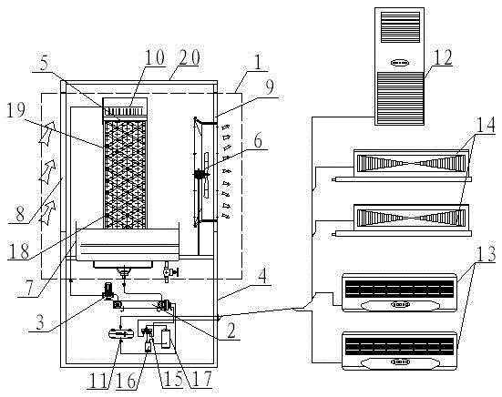
[0010] As shown in Figure 1, the present invention includes an air exchanger 1, a water-fluorine exchanger 2 and a circulating water pump 3, and the air exchanger 1 includes a housing 4, a filling chamber 5, a blower fan 6 and an ice source solution accumulation pool 7. The side walls of the housing 4 on both sides of the filling chamber 5 are provided with an air inlet 8 and an air outlet 9, the fan 6 is fixed at the air outlet 9 of the housing 4, and the ice source solution pool 7 is installed in the housing 4 and located at Directly below the filling chamber 5, the ice source solution accumulation pool 7 communicates with the liquid inlet of the water-fluorine exchanger 2, and the liquid outlet of t...


PUM


Abstract

The invention discloses an ice source heat pump multi-connected unit. The ice source heat pump multi-connected unit comprises an air exchaner, a water-fluorine exchanger, a circulating water pump, a filling chamber and an ice source solution accumulating pool, wherein an air inlet and an air outlet are formed in the shell side walls at the two sides of the filling chamber; the fan is fixed in the air outlet of the shell; the ice source solution accumulating pool is positioned rightly below the filling chamber, and is connected with a sprayer through the water-fluorine exchanger and the circulating water pump; a refrigerating agent of the water-fluorine exchanger is fed to a multi-unit air conditioner and an air pipe machine through a valve set; a refrigerating agent backflow port of the water-fluorine exchanger is communicated with a reversing four-way valve; the rest three joints of the reversing four-way valve are respectively communicated with a gas-liquid separator, a backflow pipe of an air conditioner indoor unit and an outlet of a compressor; and the gas-liquid separator is communicated with an inlet of the compressor. A refrigerant medium incapable of being frozen at subzero 30 DEG C exchanges heat with air to serve as a cold carrying agent or a heat carrying agent, so that the refrigerating or heating effect is improved, the energy consumption is reduced, and three functions of refrigeration, heating or living hot water can be provided indoors.

Description

technical field [0001] The present invention belongs to the field of ice source technology, specifically a multi-unit unit. Background technique [0002] At present, with the rapid growth of the world's population and economy, energy consumption has increased dramatically. Today, with increasingly serious environmental pollution and increasingly endangered living environment, people's desire to be green and protect the environment is becoming stronger and stronger. Now air-conditioning has basically been widely used in every household. With the use of air-conditioning, the power consumption increases sharply. Therefore, various new air-conditioning systems appear to solve the problem of increasing power consumption. The air source heat pump air conditioning system and the water source heat pump air conditioning system are the most used at present, but there are some problems in these two air conditioning system technologies. If the outside temperature of the air source heat...

Claims


Application Information

Patent Timeline
Patent Type & Authority Applications(China)
IPC IPC(8): F24F5/00F24F13/30
CPCF24F5/001F24F5/0017F24F13/30F24F2005/0025Y02E60/14
Inventor 李开年曾斌
Owner CHONGQING BINGYUANHONG ENERGY SAVING TECH DEV CO LTD
Learn More