
LED bulb

A technology of LED light bulbs and LED light sources, applied in the cooling/heating devices of lighting devices, lighting and heating equipment, road vehicles, etc., can solve the problems of low heat dissipation efficiency and slow air flow rate, and improve the flow rate and speed up the convection. The effect of speed, rapid cooling

Inactive Publication Date: 2016-03-02
XUZHOU LIFANG MECHANICAL & ELECTRICAL EQUIP MFG CO LTD
View PDF5 Cites 0 Cited by
  • Summary
  • Abstract
  • Description
  • Claims
  • Application Information

AI Technical Summary

Problems solved by technology

[0004] The existing LED lights with natural convection for LED light sources have slow air flow rate and low heat dissipation efficiency

Method used


Image

  • LED bulb

Examples


Embodiment Construction

[0011] The present invention will be described in detail below in conjunction with the accompanying drawings.

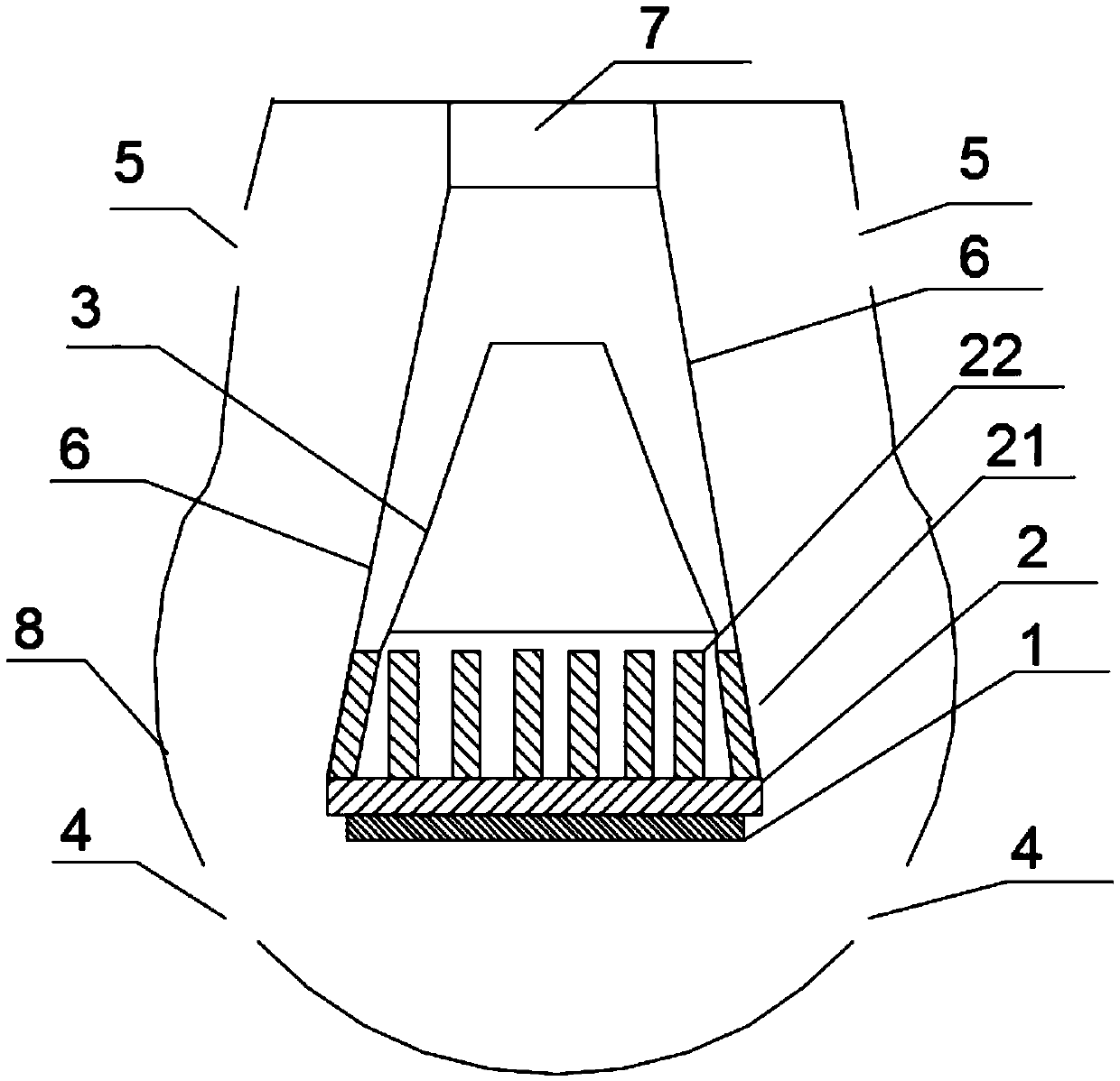
[0012] like figure 1 As shown, this embodiment includes a lamp holder 7, an LED light source 1, a housing 8, and the upper and lower ends of the housing 8 are provided with convection holes. It is fixed on the lamp holder 7, and the upper end surface of the heat dissipation plate 2 has a heat dissipation protrusion 22, and the upper end of the heat dissipation protrusion 22 is fixed with a conical glass sleeve 3, and the housing 8 is located on the upper side of the glass sleeve 3 and has two openings. Convection holes 5 , two lower convection holes 4 are opened on the part of the casing 8 located at the lower side of the LED light source 1 . Both ends of the upper surface of the heat dissipation plate 2 have protrusions 21 inclined toward the center of the heat dissipation plate.

[0013] Since the heat dissipation plate is provided with a protrusion on the end su...


PUM


Abstract

An LED bulb comprises a lamp holder (7), an LED light source (1) and a shell (8). Convection holes are formed in the upper end and the lower end of the shell (8), and the LED light source is installed on the bottom face of a heat radiation plate (2). The heat radiation plate (2) is fixed to the lamp holder (7) through a heat conducting bar (6). Heat radiation protrusions (22) are arranged on the upper end face of the heat radiation plate (2), and a glass sleeve (3) is fixed to the upper ends of the heat radiation protrusions (22). Two upper convection holes (5) are formed in the position, on the upper side of the glass sleeve (3), of the shell (8). Two lower convection holes (4) are formed in the position, located on the lower side of the LED light source (1), of the shell (8). The LED bulb can achieve fast heat convection, and the heat radiation efficiency of the LED light source can be improved.

Description

technical field [0001] The invention relates to an LED light bulb. Background technique [0002] In recent years, due to the rapid development of the LED industry, LED lamps have gradually replaced traditional lighting fixtures. A new product currently on the market has a luminous body similar to the tungsten filament of an incandescent lamp, with higher luminous efficiency and an angle of light close to that of an incandescent lamp. The conversion rate of LED lamps to convert electrical energy into light energy is only 15-35%, and the rest is converted into heat energy. The heat generated during the lighting process cannot be dissipated in time, which will greatly reduce the luminous efficiency of the light source. [0003] Existing LED heat dissipation generally adopts solid conduction heat dissipation. The heat sink is made of a large amount of aluminum, zinc alloy and other materials for stamping or die-casting; active cooling technologies such as heat pipes, nano he...

Claims


Application Information

Patent Timeline
IPC IPC(8): F21S8/10F21V29/70F21V29/83F21W101/02F21Y115/10F21W107/10
CPCF21S45/47F21W2107/10
Inventor 韩艳玲
Owner XUZHOU LIFANG MECHANICAL & ELECTRICAL EQUIP MFG CO LTD
Learn More