Injector pressure control valve

A technology of pressure control and fuel injectors, applied in the direction of machines/engines, fuel injection devices, engine components, etc., can solve problems affecting fuel atomization quality, energy loss, common rail pressure drop, etc., to avoid high-pressure fuel waste, The effect of improving the injection response rate and reducing the cost of R&D and manufacturing

Active Publication Date: 2017-09-29
CHINA NORTH ENGINE INST TIANJIN
View PDF4 Cites 0 Cited by
  • Summary
  • Abstract
  • Description
  • Claims
  • Application Information

AI Technical Summary

Problems solved by technology

[0002] For a fuel injector equipped with a traditional solenoid valve, during the fuel injection process, the low-pressure fuel return hole communicates with the high-pressure fuel inlet hole, and a considerable amount of high-pressure fuel will flow through the control chamber and flow back to the fuel tank through the solenoid valve. A portion of the high-pressure fuel has high pressure, but does no work and turns completely into heat, causing energy loss
In addition, during the fuel injection process, the connection of the inlet and outlet holes of the control chamber, the high-pressure fuel in the common rail pipe directly flows back to the fuel tank, causing the pressure of the common rail to drop, resulting in a drop in the actual fuel injection pressure, which affects the quality of fuel atomization
In addition, the choice of the diameter of the high-pressure oil inlet hole and the low-pressure oil return hole in the control chamber of the injector equipped with a traditional solenoid valve is mutually restricted. Considering factors such as the opening speed of the needle valve and the seating speed, the high-pressure oil inlet hole and the choice of low pressure oil return hole can only be a compromise of many factors

Method used


Image

  • Injector pressure control valve

Examples


Embodiment Construction

[0019] It should be noted that, in the case of no conflict, the embodiments of the present invention and the features in the embodiments can be combined with each other.

[0020] The present invention will be described in detail below with reference to the accompanying drawings and examples.

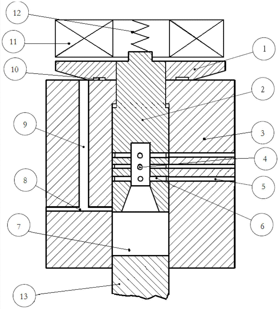
[0021] Such as figure 1 As shown, a fuel injector pressure control valve includes an armature 1, a solenoid valve core 2, a fuel injector intermediate 3, an electromagnet 11, a needle valve lifter 13, and a solenoid valve spring 12. The armature 1 is set on Below the electromagnet 11, the solenoid valve core 2 passes through the top of the armature 1 and is fixedly connected with the armature 1, and the solenoid valve spring 12 in a compressed state is arranged on the solenoid valve valve. Between the core top and the electromagnet 11, the electromagnetic valve spool 2 is arranged in the middle cavity of the injector intermediate body 3, and the electromagnetic valve spool 2 and the inj...


PUM


Abstract

The invention discloses a pressure control valve for an oil sprayer. The pressure control valve comprises an armature, a solenoid valve element, an oil sprayer intermediate, an electromagnet and a solenoid valve spring, wherein the armature is connected with the solenoid valve element; the solenoid valve element is connected with the oil sprayer intermediate in a sliding manner; the solenoid valve spring is arranged in a central hole of the electromagnet and is connected with the solenoid valve element; oil containing circular grooves and high-pressure oil inlets which are communicated with the oil containing circular grooves are formed in the solenoid valve element; a low-pressure oil return hole and a static oil drainage hole which are communicated with each other are formed in the oil sprayer intermediate; a control cavity is formed by the solenoid valve element and the oil sprayer intermediate; and the solenoid valve element slides vertically in the oil sprayer intermediate under the joint effect of solenoid force, solenoid valve spring force and hydraulic force, and the closing or opening of the high-pressure oil inlets and the low-pressure oil return hole is controlled, so that the aim of adjusting the change of hydraulic force in the control cavity is achieved. According to the pressure control valve, during an oil spraying process, no high-pressure fuel oil flows back to a fuel oil tank through the oil inlets, the oil outlet and a solenoid valve of the control cavity, so that unnecessary high-pressure fuel oil waste is avoided; and the spraying response speed of the oil sprayer is improved.

Description

technical field [0001] The invention belongs to the field of fuel injection equipment, in particular to a fuel injector pressure control valve. Background technique [0002] For a fuel injector equipped with a traditional solenoid valve, during the fuel injection process, the low-pressure fuel return hole is connected to the high-pressure fuel inlet hole, and a considerable amount of high-pressure fuel will flow through the control chamber and flow back to the fuel tank through the solenoid valve. A part of the high-pressure fuel has a high pressure, but does not do any work, and turns into heat completely, causing energy loss. In addition, during the fuel injection process, when the inlet and outlet holes of the control chamber are connected, the high-pressure fuel in the common rail pipe directly flows back to the fuel tank, causing the pressure of the common rail to drop. As a result, the actual fuel injection pressure drops and the quality of fuel atomization is affected...

Claims


Application Information

Patent Timeline
Patent Type & Authority Patents(China)
IPC IPC(8): F02M61/10F02M51/06
CPCF02M51/061F02M61/10
Inventor 孙树平奚星吴小军顾娇娇高怡
Owner CHINA NORTH ENGINE INST TIANJIN
Why Eureka
Try Eureka