Eureka AIR delivers breakthrough ideas for toughest innovation challenges, trusted by R&D personnel around the world.

Novel laminating cold foil stamping structure

A technology of cold foil stamping and film coating, applied in gold powder printing, printing, rotary printing machines, etc., can solve the problems of great impact on quality and efficiency, waste, and increased costs, so as to improve the quality and effect of cold stamping, improve the quality of cold stamping, Avoid the peeling effect

Inactive Publication Date: 2016-03-02
天津市安德诺德印刷股份有限公司
View PDF0 Cites 2 Cited by
  • Summary
  • Abstract
  • Description
  • Claims
  • Application Information

AI Technical Summary

Problems solved by technology

[0002] For intermittent rotary printing machines, during printing, due to the display of the printing plate roller structure, the reel to be printed is continuously fed, which will cause blanks on part of the substrate, causing waste and increasing costs, so the gap The intermittent design of the wet rotary printing machine is to return the blank part of the substrate and reprint it, which can reduce the purpose of saving paper; but in this link, there is a lamination cold stamping link, and the paper will return to cold stamping The effect will have an impact on the quality and efficiency of printing. It is necessary to provide a structure to ensure the cold stamping link of the film, so as to ensure the quality of cold stamping

Method used


Image

  • Novel laminating cold foil stamping structure
  • Novel laminating cold foil stamping structure

Examples


Embodiment Construction

[0022] Specific embodiments of the present invention will be described in detail below in conjunction with the accompanying drawings.

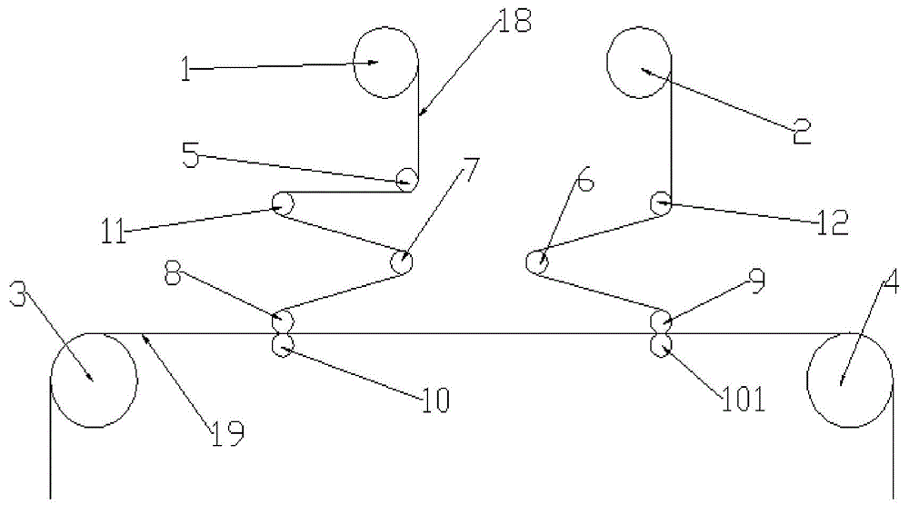
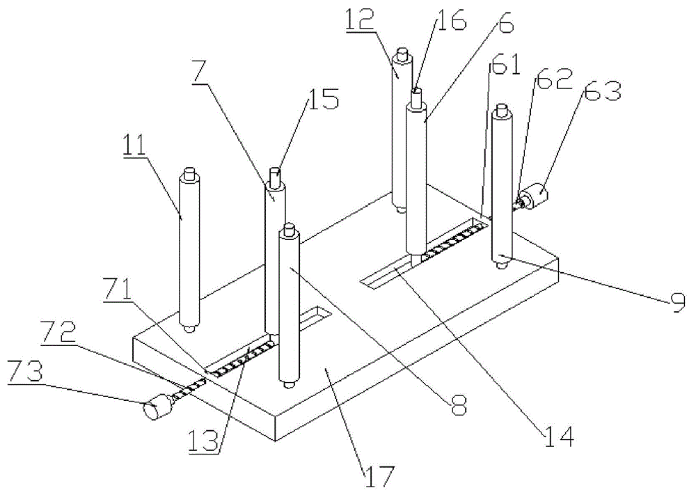
[0023] As shown in Figure 1, the present invention provides a new film-coated cold foil stamping structure including a cold foil stamping unwinding device 1, a cold stamping unit and a cold foil stamping winding device 2. The cold stamping unwinding device 1 is located at the upper left end of the cold stamping unit. The cold stamping winding device 2 is located at the upper right end of the cold stamping unit; the cold stamping unit includes the first reversing guide roller 5, the second reversing guide rail 11, the left adjustment roller 7, the embossing roller 8, the peeling roller 9, and the right adjustment roller 6 and the third reversing guide roller 12, the first reversing guide roller 5 is arranged below the cold stamping unwinding device 1, the second reversing guide roller 11 is arranged on the left lower side of the first reversing ...


PUM


Abstract

The invention provides a novel laminating cold foil stamping structure which comprises a cold foil stamping unreeling device, a cold foil stamping unit and a cold foil stamping reeling device. The cold foil stamping unit comprises a first reversing guide roll, a second reversing guide roll, a left adjusting roll, an impressing roll, a stripping roll, a right adjusting roll and a third reversing guide roll. A left attaching press roll is arranged at the lower end of the impressing roll. A right attaching press roll is arranged at the lower end of the stripping roll. The cold foil stamping unit is fixed to a fixing wall, and a left slide way and a right slide way are arranged on the fixing wall. The left adjusting roll is arranged on the left slide way, a left adjusting shaft is arranged on the left adjusting roll, and the left adjusting shaft is fixed to the left slide way. According to the novel laminating cold foil stamping structure, the cold foil stamping quality of the cold foil stamping technology in an intermittent rotary press can be improved, due to the fact that the left adjusting roll and the right adjusting roll are adjusted, cold stamped foil and printing stock conduct unreeling together during unreeling, it is avoided that the printing stock is stripped from the cold stamped foil, and the cold stamping quality and the effect of cold foil stamping are effectively improved.

Description

technical field [0001] The invention relates to the field of printing, in particular to a novel film-coated cold foil stamping structure. Background technique [0002] For intermittent rotary printing machines, during printing, due to the display of the printing plate roller structure, the reel to be printed is continuously fed, which will cause blanks on part of the substrate, causing waste and increasing costs, so the gap The intermittent design of the wet rotary printing machine is to return the blank part of the substrate and reprint it, which can reduce the purpose of saving paper; but in this link, there is a lamination cold stamping link, and the paper will return to cold stamping The effect will have an impact on the quality and efficiency of printing. It is necessary to provide a structure to ensure the cold stamping link of the film, so as to ensure the quality of cold stamping. Contents of the invention [0003] The problem to be solved by the present invention...

Claims


Application Information

Patent Timeline
IPC IPC(8): B41F19/06B41G1/04
Inventor 李智君
Owner 天津市安德诺德印刷股份有限公司
Why Eureka
Eureka Blog
Learn More