
Multi-pipe connecting die for die pressing pipes

A pipe connection and mold technology, applied in the field of multi-pipe connection molds for molded pipes, can solve the problems of weak connection, poor sealing performance, cracking, etc., and achieve the effect of simple and reasonable structure design and easy production and operation.

Inactive Publication Date: 2016-03-02
荆州洪湖科技有限公司
View PDF4 Cites 2 Cited by
  • Summary
  • Abstract
  • Description
  • Claims
  • Application Information

AI Technical Summary

Problems solved by technology

[0003] In the current existing technology, both the mold for making molded pipes and the molded pipes made of molds have certain defects in practical application. The specific performance is that the existing molds are composed of two parts: A mold and B mold. , where A mold and B mold respectively include A die, A punch and B die, and B punch. The molded tubes made by A mold and B mold are both 1 meter long, and the two molded tubes are joined together The final fixed length is 2 meters. In practice, the drainage pipes of many drainage systems are larger than 2 meters. The fixed length of 2 meters usually cannot meet the actual needs.
In addition, the molded tubes produced by the existing molds are generally connected using the principle of thermal expansion and contraction, that is, after two 1-meter molded tubes are produced, they are quickly connected when the molded tubes are still at a relatively high temperature. After cooling down, the two molded tubes are butted by cold shrinkage. Although this connection method is easy to operate, it has the disadvantages of weak connection and poor sealing performance, and cracks and water leakage will occur during use.

Method used


Image

  • Multi-pipe connecting die for die pressing pipes
  • Multi-pipe connecting die for die pressing pipes
  • Multi-pipe connecting die for die pressing pipes

Examples


Embodiment Construction

[0024] The present invention will be further described below in conjunction with the accompanying drawings and embodiments.

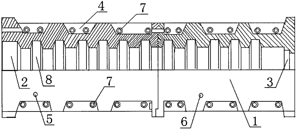
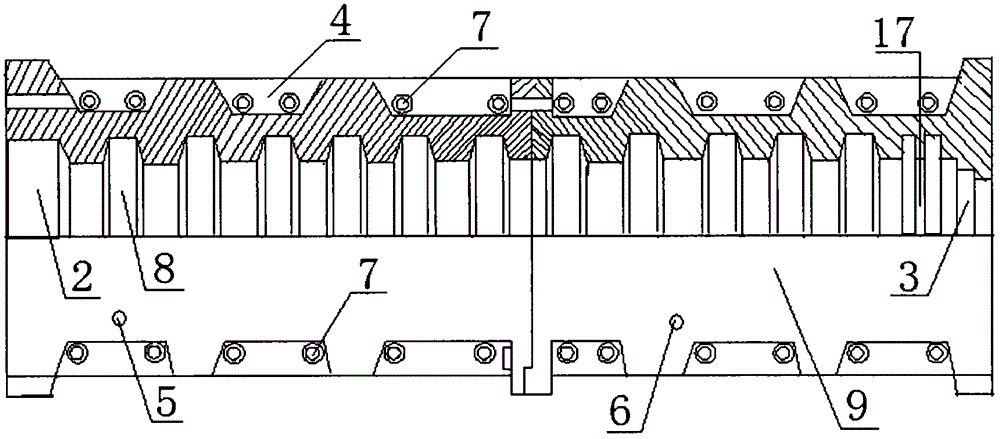
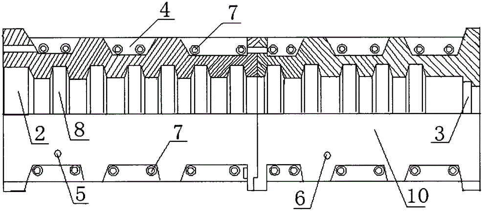
[0025] figure 1 It is the structural representation of the A die of the present invention, figure 2 It is a structural schematic diagram of B die of the present invention, image 3 It is the structural representation of A punch of the present invention, Figure 4 It is the structural representation of the B punch of the present invention, Figure 5 It is the structural representation of C die of the present invention, Image 6 It is a structural schematic diagram of the C concave mold of the present invention.

[0026] Please refer to the accompanying drawings, the molded pipe multi-pipe connection mold provided by the present invention includes a mold A and a mold B, the length of the molded pipe made by the mold A and the mold B is 2 meters after butt joint, and the mould A is formed by the A mold Die 1 and A punch, the B die is composed of B di...


PUM

PropertyMeasurementUnit
Diameteraaaaaaaaaa

Abstract

The invention discloses a multi-pipe connecting die for die pressing pipes. The die comprises a die body A and a die body B. The die body A is composed of a female die A and a male die A. The die body B is composed of a female die B and a male die B. An inner muzzle bell cavity is formed in one end of the female die A and an annular spigot is arranged at the other end of the female die A. An inner muzzle bell cavity is formed in one end of the female die B and the other end of the female die B is provided with an annular spigot and a sealing ring groove. The male die A and the male die B each comprise a pipe body and an inner cavity. The multi-pipe connecting die for the die pressing pipes further comprises die bodies C and the number of the die bodies C can be increased according to actual requirements; and each die body C comprises a female die C and a male die C, an inner muzzle bell cavity is formed in one end of each female die C, an annular spigot is arranged at the other end of each female die C, and each male die C comprises a pipe and an inner cavity. By the adoption of the multi-pipe connecting die for the die pressing pipes, the die bodies C are additionally arranged and the number of the die bodies C can be increased according to the actual requirements, the defect that only die pressing pipes with the length of 2 m can be produced in the prior art is overcome, and therefore the die pressing pipes can be more widely applied to drainage facility construction of municipal engineering and the like.

Description

technical field [0001] The invention relates to a mold for making molded pipes, in particular to a multi-pipe connection mold for molded pipes used for making urban drainage and sewage molded pipes. Background technique [0002] Plastic molded pipes are widely used in urban drainage systems. Plastic molded pipes have many advantages such as light weight, corrosion resistance, smooth inner wall, small friction coefficient, good sealing performance, long service life, easy installation and disassembly, and convenient transportation. In the field of mechanical mold making, there are molds specially used for making plastic drainage pipes. The mold is mainly composed of a die and a punch. [0003] In the current existing technology, both the mold for making molded pipes and the molded pipes made of molds have certain defects in practical application. The specific performance is that the existing molds are composed of two parts: A mold and B mold. , where A mold and B mold respec...

Claims


Application Information

Patent Timeline
IPC IPC(8): B29C33/00B29C65/70
Inventor 杜元浩
Owner 荆州洪湖科技有限公司
Learn More