
Clamp used for water cutting of side frame casting of railway wagon

A railway freight car and water jet cutting technology, which is applied in the field of machining, can solve the problems of the side frame casting riser being harmful, polluting the environment, and the side frame casting being unable to achieve stable positioning.

Active Publication Date: 2016-03-02
HARBIN INST OF TECH
View PDF8 Cites 0 Cited by
  • Summary
  • Abstract
  • Description
  • Claims
  • Application Information

AI Technical Summary

Problems solved by technology

[0004] The present invention solves the problem that the existing side frame casting riser needs to cut the channel of the metal liquid after the casting is completed. The traditional method is harmful to the cutting of the side frame casting riser and pollutes the environment. Although the high-pressure water jet cutting technology makes up for the disadvantages of the traditional method Disadvantages, but the problem that the side frame castings cannot be stably positioned in the water tank, and then a fixture for water jet cutting the side frame castings of railway wagons is proposed

Method used


Image

  • Clamp used for water cutting of side frame casting of railway wagon
  • Clamp used for water cutting of side frame casting of railway wagon
  • Clamp used for water cutting of side frame casting of railway wagon

Examples


specific Embodiment approach 1

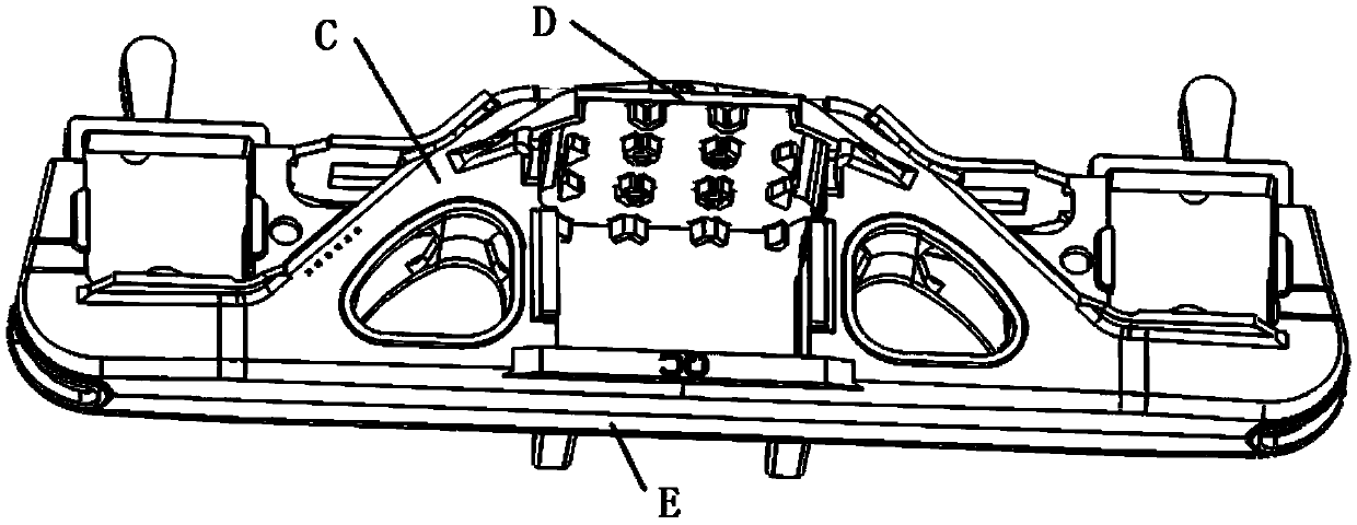
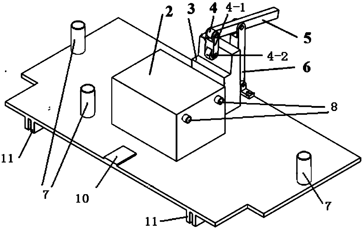
[0019] Specific implementation mode one: combine figure 1 , figure 2 , image 3 , Figure 4 , Figure 5 with Image 6 Describe this embodiment. This embodiment includes a support base 1, a first positioning block 2, a second positioning block 3, a pressure wheel member 4, a pressing rod 5 and a connecting rod 6. There are three The first positioning nail 7, the top surface of the support base 1 is a three-nail positioning surface C' matched with the positioning surface C of the bottom surface of the side frame casting, and the three-nail positioning surface C' is sequentially provided with first The positioning block 2, the second positioning block 3 and the connecting rod 6, the gap between the first positioning block 2 and the second positioning block 3 is set, the first positioning block 2 is a rectangular block, and one side of the first positioning block 2 There are two second positioning nails 8 arranged side by side. One side of the first positioning block 2 is a ...

specific Embodiment approach 2

[0022] Specific implementation mode two: combination image 3 with Figure 4 To illustrate this embodiment, in this embodiment, the three first positioning nails 7 surround and form a triangular positioning surface, and the first positioning block 2 is located on the triangular positioning surface.

[0023] The location of the first positioning block 2 on the triangular positioning surface is specifically set for the structure of the bottom surface of the side frame casting, so that the positioning effect of the first positioning block 2 on the bottom surface of the side frame casting is more accurate. Other unmentioned structures and connections are the same as those in the first embodiment.

specific Embodiment approach 3

[0024] Specific implementation mode three: combination image 3 Describe this embodiment, the pressure wheel part 4 in this embodiment includes a pressure plate 4-1 and a roller 4-2, the pressure plate 4-1 is arranged in parallel with the connecting rod 6, and the lower end of the pressure plate 4-1 is provided with a roller 4-2. 2. The roller 4-2 rolls on the side of the second positioning block 3 opposite to the first positioning block 2, and the upper end of the pressing plate 4-1 is hinged to one end of the pressing rod 5. Other unmentioned structures and connections are the same as those in the first or second embodiment.


PUM


Abstract

The invention discloses a clamp used for water cutting of a side frame casting of a railway wagon and relates to a clamp. A channel for cutting liquid metal is needed for a feeder head of an existing side frame casting after the casting is finished. Harm is great and the environment is polluted when the feeder head of the side frame casting is cut through a traditional method. Although the defect of the traditional method is overcome by cutting through a high-pressure water jet technique, the side frame casting can not be located stably in a water tank. According to the clamp, the top face of a support base is a three-nail locating face C' matched with the bottom face locating face C of the side frame casting, one side face of a first locating block is two-locating-nail locating face A' matched with the middle side face locating face A of the side frame casting, and the end face, close to a second locating block, of the first locating block is a single-nail locating face B' matched with the middle bottom face locating face B of the side frame casting. A top face D' supporting a flange in an auxiliary mode is matched with the top bottom face D of the side frame casting. The gap between the second locating block and a connection rod is matched with the bottom clamping face E of the side frame casting. The clamp is suitable for the process of cutting of the side frame casting.

Description

technical field [0001] The invention relates to a jig for cutting side frame castings of railway wagons, which belongs to the field of mechanical processing. Background technique [0002] As the blank of many large parts, the casting is the basis of many large parts, and the casting riser is the channel of the metal liquid during casting processing, which needs to be cut after the casting is completed. The traditional method of cutting the riser of castings is to use oxy-acetylene flame processing to cut the riser by using the high temperature generated when acetylene burns. The advantage of this cutting method is mainly the high efficiency, but the disadvantages are also very obvious. During oxy-acetylene flame cutting, a large amount of exhaust gas will be generated, which will cause harm to the operator, and the waste residue generated at the same time will pollute the environment. The surface after cutting is rough and not smooth. Therefore, it is necessary to choose a ...

Claims


Application Information

Patent Timeline
Patent Type & Authority Applications(China)
IPC IPC(8): B24C9/00B22D31/00
CPCB22D31/00B24C9/00
Inventor 周亮陈剑箫金光远朱波王娜军
Owner HARBIN INST OF TECH
Learn More