Laminate for light emitting device and process of preparing same
A light-emitting device and light extraction layer technology, applied in the field of optical devices, can solve the problems of increased light loss and reduced visible light transmittance, and achieve the effect of uniform turbidity ratio
- Summary
- Abstract
- Description
- Claims
- Application Information
AI Technical Summary
Problems solved by technology
Method used
Image

Examples
preparation example Construction
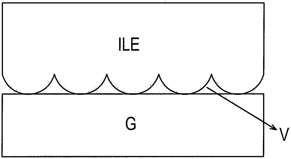
[0082] figure 2 It is a flow chart illustrating a method for preparing a laminate for a light emitting device according to an embodiment of the present invention. The meaning of "ILE", "V" and "G" and figure 1 The same as those disclosed in . "F" indicates glass powder before sintering, and "EC" indicates ethyl cellulose.
[0083] First, a substrate containing potassium or having been surface-treated with potassium, or coated with a layer of a potassium-containing mineral is prepared (step (a)). The basic physical properties necessary for the substrate, such as the refractive index, are as described above. A paste comprising glass frit, preferably without scattering particles, is applied on the substrate (step (b)), and then dried (step (c)). The composition of the glass frit included in the paste is as described above, and the paste includes the glass frit in an amount of 70 to 80% by weight and the remaining composition of the paste includes a binder, a solvent, and the...
example 1
[0095] Prepared as described in Example 10 of U.S. Patent No. 6,905,991 having a thickness of 0.7 mm and comprising 5 wt% Na 2 O and 6wt%K 2 O glass substrate. Prepare a slurry, the slurry includes 75wt% glass powder based on the total amount of the slurry, 3wt% ethyl cellulose as a binder and 22wt% solvent, the glass powder includes 70wt% based on the total weight of the glass powder %Bi 2 o 3 , 3wt%Al 2 o 3 , 10wt%ZnO, 7wt%SiO 2 , 9wt%B 2 o 3 and 1wt%Na 2 O. The refractive index at 550nm is 1.91.
[0096] The glass substrate was cleaned, and then a paste including glass frit was applied on the glass substrate by a screen printing method. The solvent was evaporated by drying the coated slurry in an oven at a temperature of 130°C for about 20 minutes. Thereafter, ethyl cellulose contained in the dried slurry was removed by leaving the dried slurry at a temperature of 430° C. for about 20 minutes.
[0097] The prepared glass frit layer was sintered at a temperature...
example 2
[0101] A laminate for a light emitting device including an interfacial void layer was prepared in the same manner as in Example 1, except that the sintering temperature was set to 550°C.
[0102] Example 3: Preparation of laminates for light-emitting devices with potassium-containing glass substrates
PUM
| Property | Measurement | Unit |
|---|---|---|
| Thickness | aaaaa | aaaaa |
| Total thickness | aaaaa | aaaaa |
| Thickness | aaaaa | aaaaa |
Abstract
Description
Claims
Application Information
 - R&D
- Intellectual Property
- Life Sciences
- Materials
- Tech Scout
- Unparalleled Data Quality
- Higher Quality Content
- 60% Fewer Hallucinations
Browse by: Latest US Patents, China's latest patents, Technical Efficacy Thesaurus, Application Domain, Technology Topic, Popular Technical Reports.
© 2025 PatSnap. All rights reserved.Legal|Privacy policy|Modern Slavery Act Transparency Statement|Sitemap|About US| Contact US: help@patsnap.com